The computation of a Working Point
The computation of a Working Point (If, I, Ψ, N) for evaluating the performance of the wound field synchronous machines
Positioning and objective
The aim of the test “Working point – Sine wave – Motor – If, I, Ψ, N” is to characterize the behavior of the machine when operating at the targeted input values If, I, , N (magnitude of field current, magnitude of current, control angle, speed).
These three inputs are enough to impose a precise working point.
For instance, a working point can be chosen on the efficiency map by identifying the field current, current, the control angle, and the speed with different curves or maps displayed in the “Performance mapping / Sine wave / Motor / Efficiency map” test. Then, the “Working point – Sine wave – Motor – If, I, Ψ, N” test allows to compute the performance for this working point.
The results of this test give an overview of the electromagnetic analysis of the machine, considering its topology.
The general data of the machine, like the machine constant and power balance, are computed and displayed. The motor convention is used to build the model.
The magnetic flux density is also computed in every region of the machine’s magnetic circuit to evaluate the design.
- “Fast computation mode” is perfectly suited for the pre-design step (Hybrid model based on Magneto-Static Finite Element computations and Park transformation theory)
- “Accurate computation mode” is perfectly suited for the final design step (Pure Finite Element modeling based on transient computations)
Here is an overview of the test, as shown below.
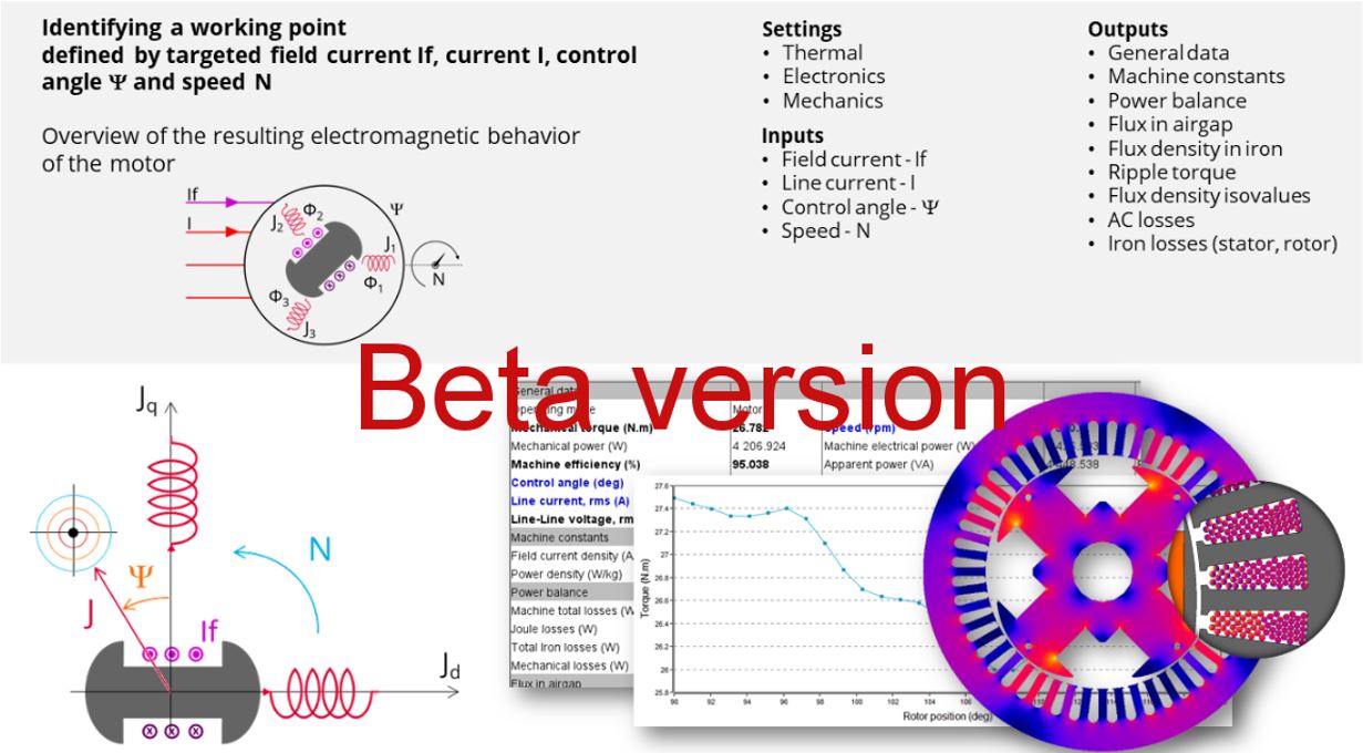 |
| Working point – Sine wave – Motor – If, I, Ψ, N – Synchronous Machines with wound field – Inner salient pole - Inner rotor (SMWF-ISP-IR) - Overview |
User inputs
The four main user input parameters are the field current, supply line current, control angle, speed, and computation mode. In addition, the temperatures of the windings must be set.
Main outputs
Test results are illustrated with data, graphs, and tables.
- Machine performance – Base speed point
- General data
- Machine constants
- Power balance
- Flux in airgap
- Flux density in iron
- Power electronics
- Inverter
- Working point
- Ripple mechanical torque
- Working point
- Ripple mechanical torque versus rotor angular position
- Flux density in airgap versus rotor angular position
- Mechanical torque versus rotor angular position
- Mechanical torque harmonic analysis
- Flux density in airgap versus rotor angular position
- Flux density in airgap harmonic analysis
- Field voltage versus rotor angular position
- Field current versus rotor angular position
- Phase voltage versus rotor angular position
- Phase voltage harmonic analysis
- Phase current versus rotor angular position
- Phase current harmonic analysis
- Isovalues
Main principles of computation
The aim of this test in motor convention is to give a good overview of the electromagnetic potential of the machine by characterizing the working point according to the field current, line current, control angle, and speed set by the user.
In addition, ripple torque at the working point is also computed.
- “Fast computation mode” is perfectly suited for the pre-design step to explore the space of solutions quickly and easily (Hybrid model based on magnetostatic FE computations and Park transformation).
- “Accurate computation mode” is perfectly suited for the final design step because it allows for getting more accurate results and to compute additional quantities like the AC losses in winding and rotor iron losses (Pure FE model based on transient computations).
Fast computation mode
To compute the working point, the principle consists of positioning the salient pole towards the reference phase axis by considering the targeted control angle.
At the same time, the targeted field current, line current, and speed are imposed.
Then, the resulting behavior of the machine can be simulated, and all the main electromagnetic characteristics of the machine can be deduced by using Park’s transformation and associated electric equations.
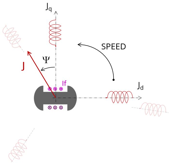 |
| Salient pole and reference phase axis Positioning – Motor convention |
- “Yes” is selected: The analysis of the electromagnetic behavior is done over one ripple torque period.
- “No” is selected: The analysis of the electromagnetic behavior is done through a dedicated static computation (1 rotor position to be considered) for the computed working point (with field current, line current, control angle, and speed obtained for the working point).
For more information, refer to MotorFactory_2024_SMWF_ISP_IR_3PH_Test_WorkingPoint.pdf.
Accurate computation mode
Working point computation is based on a transient magnetic finite element simulation over a half, one, or several electrical periods for a given set of inputs: field current, line current, control angle, and speed, defined as for the Fast computation mode.
Thus, all the main electromagnetic characteristics of the machine can be deduced accurately.
All the main quantities are directly computed from the Flux® software in the framework of a transient magnetic finite element simulation.
For more information, refer to MotorFactory_2024_SMWF_ISP_IR_3PH_Test_WorkingPoint.pdf.