The Characterization / Model / Maps
The Characterization / Model / Maps for characterizing the wound field synchronous machines.
Positioning and objective
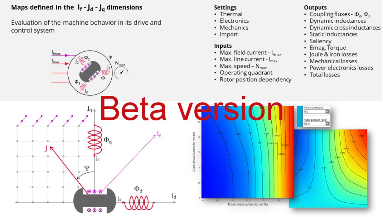
The aim of the test “Characterization - Model - Motor - Maps” is to give maps along the three dimensions, If-Jd-Jq, for characterizing the 3-Phase synchronous machines with wound field.
These maps allow for predicting the behavior of the electrical rotating machine at a system level.
In this test, engineers will find a system integrator and / or control-command tool adapted to their needs and able to provide accurate maps ready to be used in system simulation software like Activate.
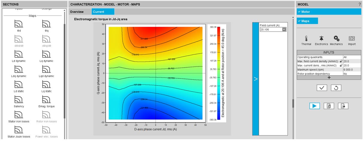
Here is an overview of the test, as shown below.
 |
| Characterization / Model / Maps – Wound field Synchronous Machines – Inner salient pole - Inner rotor (SMWF-ISP-IR) Overview |
User inputs
Maps are mainly function of the following user inputs: the maximum value of the field current, the maximum value of the line current, the speed, the number of quadrants to be considered, and the rotor position dependency.
Among the standard inputs, the operating quadrants can be selected. Options allow computing and displaying 1, 2, or 4 quadrants.
This allows defining the quadrants in the Jd - Jq plane where the test will be carried out.
By default, the considered quadrants are “1st and 2nd” (i.e., the grid is defined for both negative and positive values of the current in the d axis and positive ones in the q axis). This option is chosen as the default because the Synchronous Machine with wound field heritages the characteristics of both Synchronous Machine with Permanent Magnets and Reluctance Synchronous Machines which work respectively in the second and first quadrant in the motor operating mode.
Please see additional information in the section below (the import button allowing sharing the data simulated in Flux between model map and efficiency tests).
Main outputs
Different kinds of outputs are displayed like data, maps, and curves.
Here is a list of results that can be provided and displayed within the framework of this test.
- Flux linkage
- D-axis flux-linkage Фd
- Q-axis flux-linkage Фq
- Flux linkage derivative (only when the rotor position dependency is considered)
- D-axis flux-linkage derivative with respect to the rotor position dФd/dθr
- Q-axis flux-linkage derivative with respect to the rotor position dФq/dθr
- Inductance
- D-axis inductance (dynamic, cross dynamic and static)
- Q-axis inductance (dynamic, cross dynamic and static)
- Saliency
- Electromagnetic torque Tem
- Losses
- Stator iron losses WironStator versus speed
- Rotor iron losses WironRotor versus speed (only when the rotor position dependency is considered)
- Total losses Wtotal versus speed
Maps in the two dimensions Jd - Jq
- Losses
- Joule losses WCus in stator winding
- Power electronics losses
Curves
- Field current flux and cross effect flux curve versus Jq
- Joule losses WCur in rotor winding versus field current
- Mechanical losses versus speed versus speed
 |
|
Characterization / Model / Maps – Wound field Synchronous Machines – Inner salient pole - Inner rotor (SMWF-ISP-IR) Inputs / Outputs in the test area - Illustration |
Main principles of computation
One of the goals is to compute the D-axis and Q-axis flux linkage in the Jd, Jq planes at different levels of If between zero and the maximum value of If.
At each level of If, a grid of values (Jd, Jq) is considered. Finite Element modeling (Flux® software – Magnetostatic application) is then performed at every node of the grid. The corresponding flux linkage through each phase is extracted (a, b, c) through the corresponding phases (a, b, c).
D-axis flux-linkage component - d and Q-axis flux-linkage component - q are deduced according to Park’s transformation.
Next, the other outputs listed in the previous section are derived from analytical formulars.
For more details, refer to MotorFactory_2024_SMWF_ISP_IR_3PH_Test_Characterization.pdf.
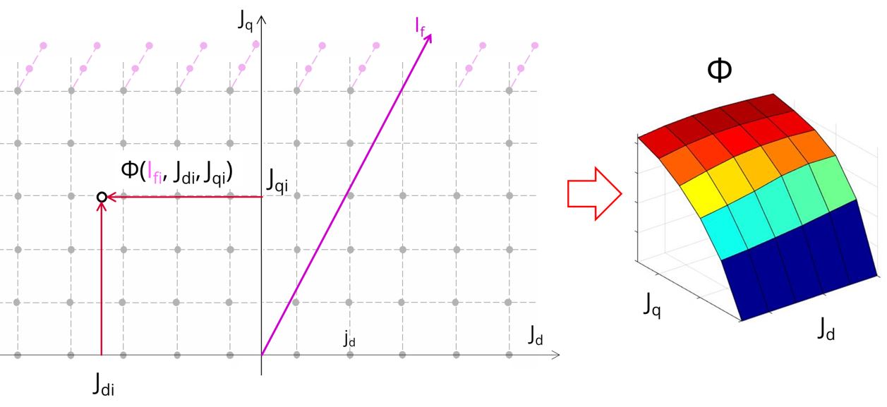 |
| Computation on a grid in Jd, Jq plane at a level of If |
Half electrical period computation for the Characterization / Model / Maps test of synchronous machines
The user input “No. computed elec. periods” (Number of computed electrical periods only required with rotor position dependency set to “Yes”) influences the computation time of the results. A new option for this input has been added allowing the computation in a half electrical period and hence reducing the computation time by a half while maintaining the identical accuracy.
Illustrations of results depending on the user’s inputs dealing with “No. computed elec. periods” (“0.5“ or “1”).
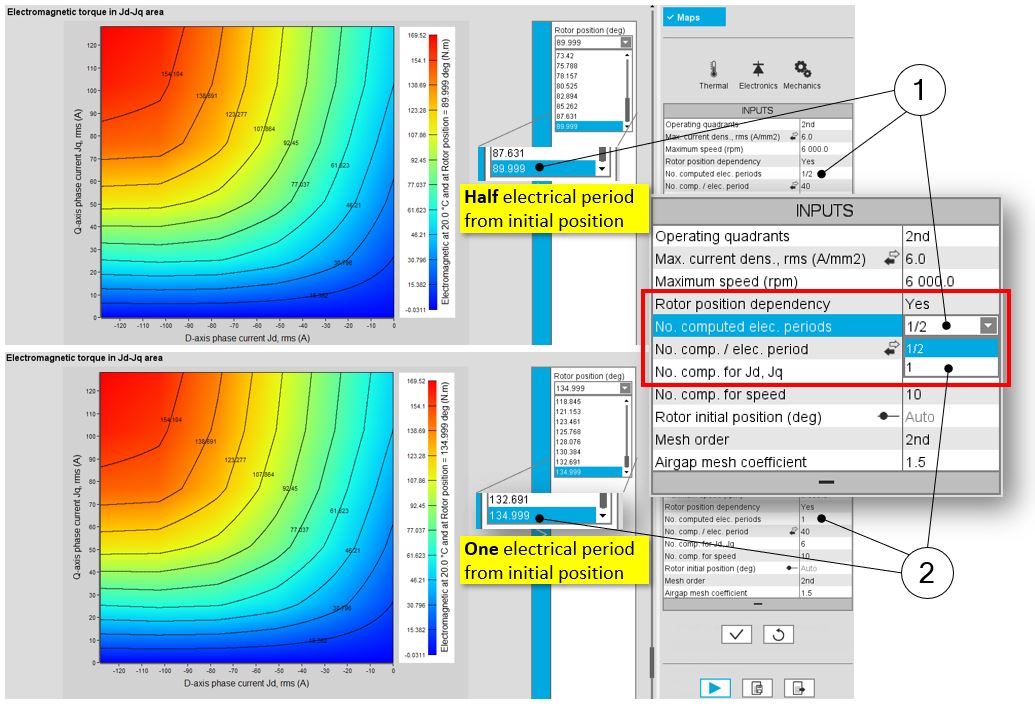 |
|
Electromagnetic torque in Jd - Jq area Maximum rotor angular position with half electrical period option (1) in the drop-down menu, and maximum rotor angular position with one electrical period option (2) in the drop-down menu |