Thermal scheme - Export to Flow Simulator
Flow Simulation export for Inner Rotor Permanent Magnet Synchronous Machines
Introduction
The aim of the export “Advanced Tools - Flow Simulator – Steady State” is to represent the thermal behavior of the machine through a customizable lumped thermal parameter model coupled with a flow network when necessary.
The resulting model is a 3D representation of a steady state thermal circuit built in Flow SimulatorTM, it corresponds to the thermal model used in Flux Motor® to run both thermal and coupled tests.
User inputs and settings
- Speed
- Motor losses
- Stator Joule losses
- Stator iron losses
- Magnet losses
- Rotor iron losses
- Mechanical losses
- External fluid temperature.
Generalized lumped thermal network.
The proposed thermal network is based on a general schema where the number of thermal resistances is fixed for some well-known regions in which geometrical changes can be modelled through variable parametrization. These regions are the shaft, the bearings, and the housing (endcaps included).
On the contrary, the local grid of some regions is highly dependent on the chosen topology and should be particularized to achieve the essential goals of maximum customization and versatility during the design stage. These regions are mainly the rotor and the stator (including the winding). Due to their high interaction with these areas the airgap and the end-spaces also require a customized grid.
The global network is displayed in a 3D view in Flux Simulator, and for clarity the different regions are associated with groups. Resistances can either be hidden inside their groups or expanded, as shown in the images below. This dual view assures, at the same time, the possibility to show a meaningful global view containing the main heat paths or, on the contrary, to have the deepest insight into one or several regions and to study in detail their configuration as explained in section dedicated to the "Customizable stator and rotor grids – The constellation method". Each group can be expanded or collapsed independently.
Once in Flow SimulatorTM the thermal circuit can be solved and any kind of modification in thermal resistance values or grid connections can be added.
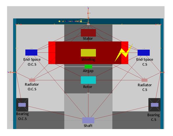 |
| Axial projection of the thermal grid exported to Flux SimulatorTM. Global view |
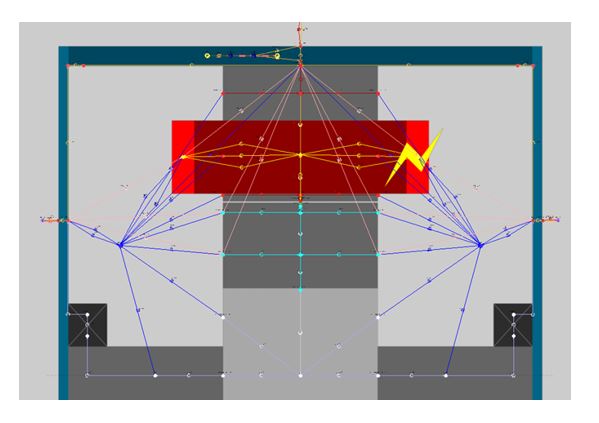 |
| Axial projection of the thermal grid exported to Flux SimulatorTM. Expanded view. |
Customizable stator and rotor grids – The constellation method
Stator and rotor geometries, especially the latter, are subject to big changes during predesign, even for a fixed number of slots or poles. Different shapes and number of magnets per pole, the existence of holes in the active parts and of shoes next to the airgap are usual. These modifications, which have an important impact on the machine’s performance, are usually difficult to parametrize.
- Since only radial electric machines are considered, the radial cut of rotor and stator are defined as rotor part and stator part, respectively. These parts are composed of different surfaces, which are represented by its material (generally steel, air, magnets or conductor) and its central point (i.e., its barycenter).
- Barycenters of neighboring surfaces will be connected by a thermal resistance. These resistances will form the part constellation. Thermal resistances between non-neighboring surfaces are supposed to be infinite.
- Surfaces in contact with external frontiers will be connected to them by thermal resistances (i.e., in the radial plane these frontiers are the airgap and the shaft for the rotor part, and the airgap and the frame for the stator part).
- It is considered that every surface in stator and rotor parts is in contact with both end-spaces; therefore a thermal resistance must link them to these regions. These resistances are the only ones that are not contained in the considered radial plane.
The generation of the rotor and stator thermal constellations is developed from their associated parts, as defined in Altair® FluxMotor®.
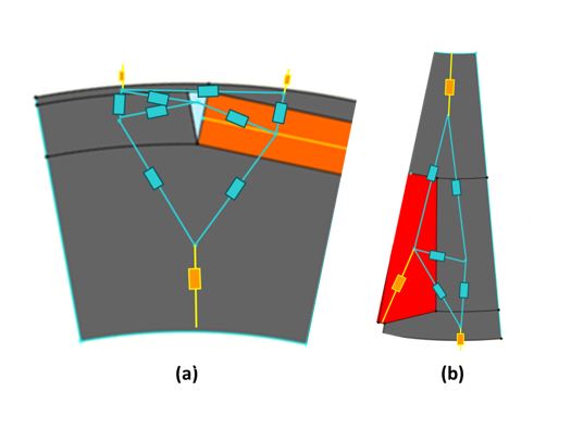 |
|
Thermal constellation of a rotor (a) and stator (b) part. In blue, thermal resistances link internal surfaces. In yellow, resistances link surfaces with part frontiers. |