Design
Saliency topology
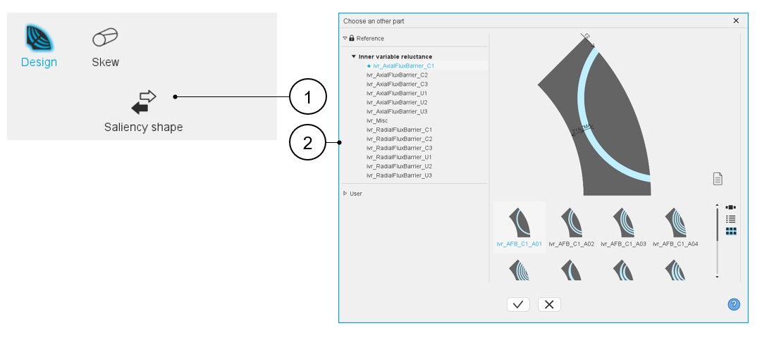
Choosing a new saliency topology is possible by clicking on the "Saliency shape" button. See the section “Choose part” for additional information. This opens a dialog box, allowing access to the saliency libraries.
It allows visualizing, comparing, choosing, and importing another saliency topology to modify in the current machine design.
 |
|
|---|---|
| 1 | Saliency shape button allows accessing the slot libraries to change the saliency topology. |
| 2 | Dialog box to visualize and to select the topologies of saliencies from the saliency part libraries. |
Inputs / Outputs
 |
|
|---|---|
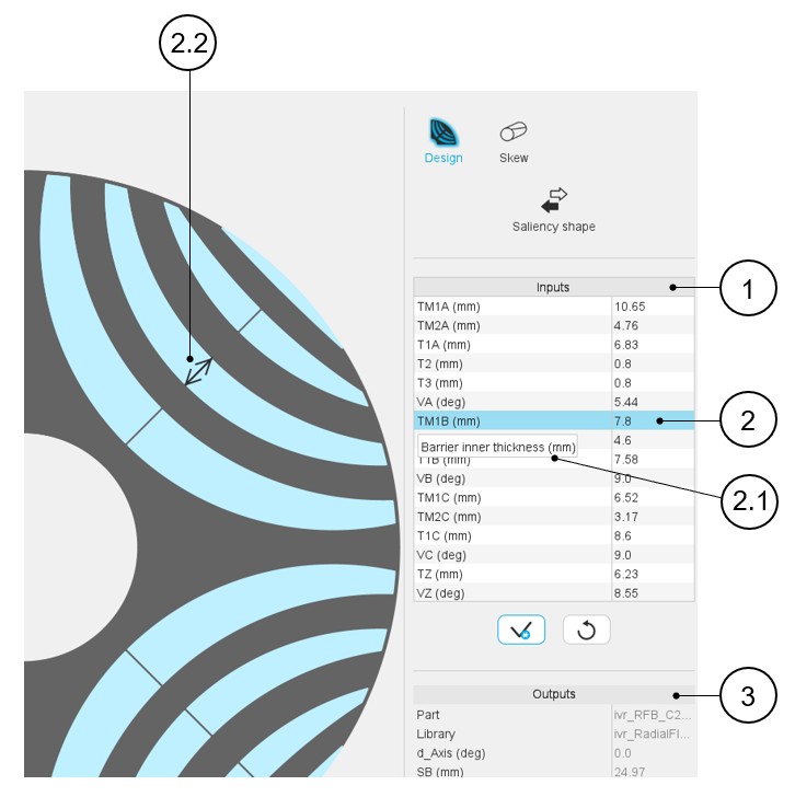
| 1 | User input parameter fields to enter the value. |
| 2 | Selecting a parameter highlights it. |
| 2.1 | Selecting a parameter displays the corresponding tooltip which completes information about the parameter. |
| 2.2 | Select a parameter label that displays the corresponding arrow on the picture. |
| 3 | Output parameters (read only data) to complete the description of
the topology. Note: The name of the part and
its original library are mentioned. |
Saliency physical properties
- List of possible elementary regions for saliencies
Here is an example of regions of inner saliency part.
Table 3. Example of regions for inner saliency part 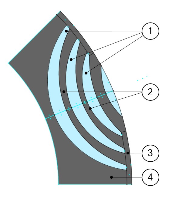
1 Flux barrier 2 Web 3 Bridge 4 Yoke Here is a list of possible elementary regions for an inner saliency:- Yoke, Web, Bridge, Pole core, Pole shoe, Interpole
- Flux barrier, Hub, Edge
- Mechanical device to represent rivet for example
- Ferromagnetic wedge
- Hole or Slit
- Cooling hole
- Rotor D-Axis location
The rotor d-axis location is characterized by the saliency topology.
Here is the below representation of the rotor and stator phase relative position.
The relative angular position between the axis of the stator phase 1 (reference phase) and the rotor D-axis position must be controlled to perform the tests.
The winding axis of the reference phase is defined from the phase shift of the first electrical harmonic of the magneto motive force (M.M.F.).
This allows us to define the working point of the machine.
Figure 1. Definition of rotor initial position – Rules for direction 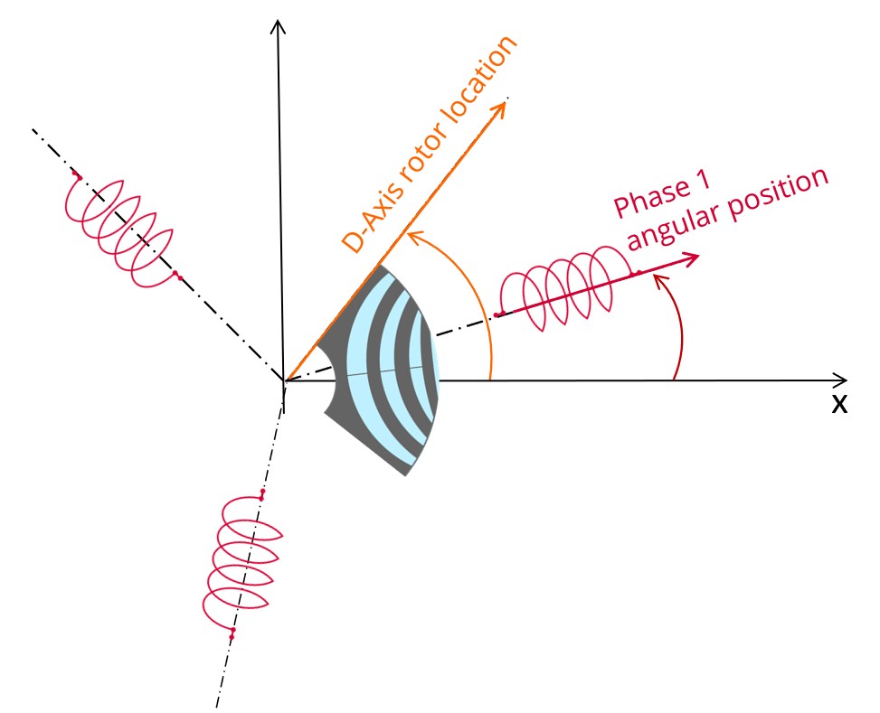
Figure 2. Example of the rotor d-axis location: d-Axis = 0 degree 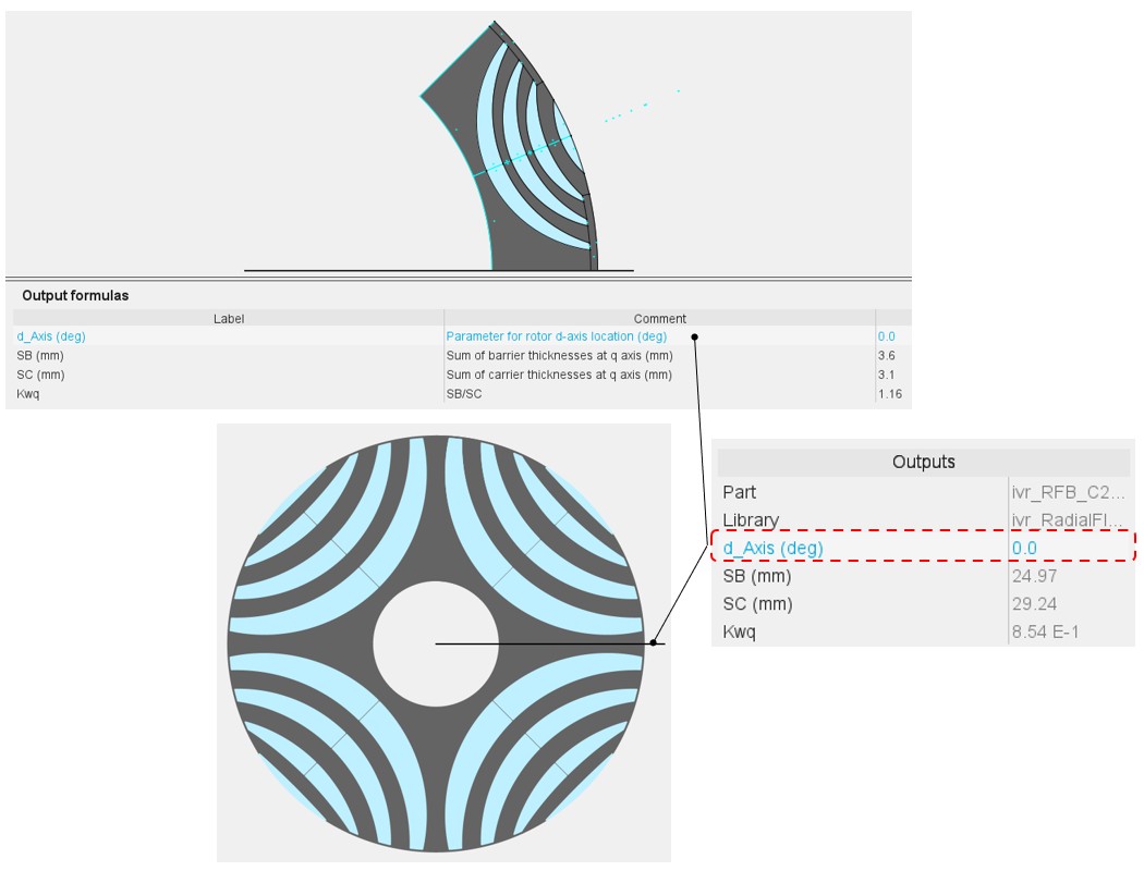
The rotor d-axis location is an output parameter (read only data) of saliency parts. It completes the description of the topology, and it is automatically used to define the relative position between the axis of the stator phase 1 (reference phase) and the rotor D-axis position for performing the tests when needed.
Figure 3. Example of the rotor d-axis location: d-Axis = 45 degrees (if the rotor yoke, in black, is built with ferromagnetic material) 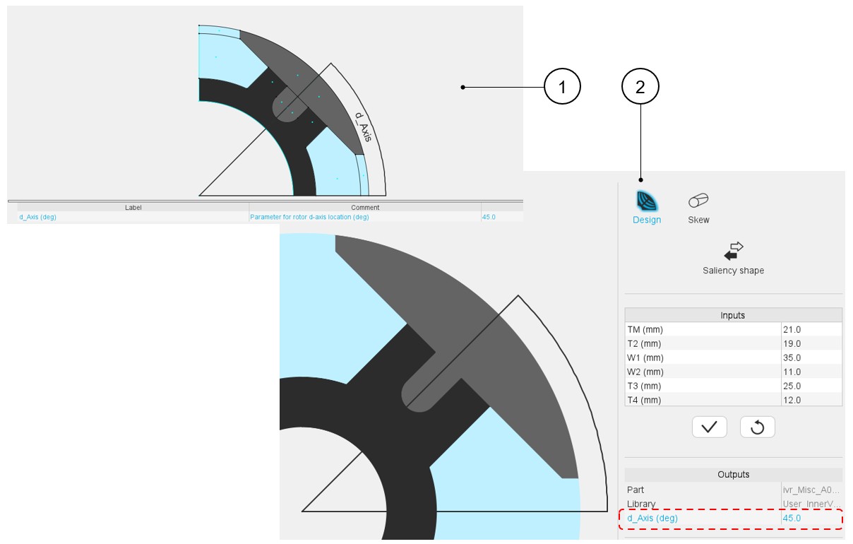
- Faces and regions of slots
This section contains a description of all the faces and regions defined and used in the saliency model.
Each face is defined by a location point. The coordinates of these points are defined in a general coordinate system.
The point must be within the corresponding face for all the values of user input parameters. Each face has a label and a nature. The nature of faces defines the corresponding regions.
The physical properties of regions are linked to the materials that can be used to build them. The table below gives the physical properties of saliencies.
Figure 4. Physical properties of Saliency regions and associated materials 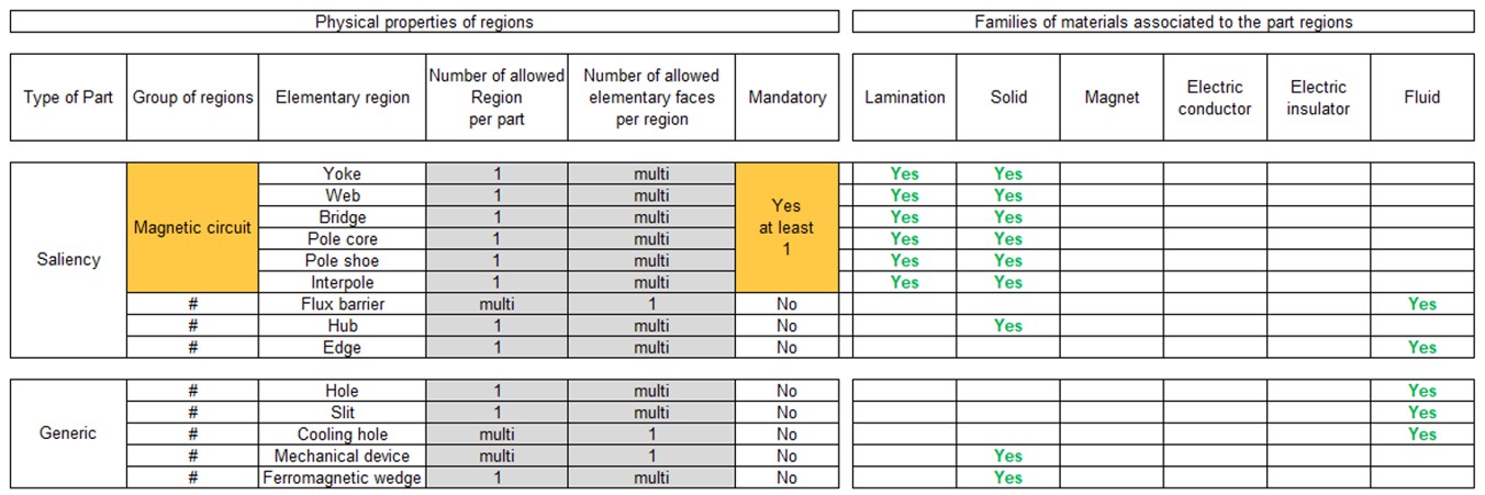
Note: When the regions are grouped (see the group of regions above), the same material is associated with all the regions grouped.Note: The possible materials associated with the regions shown above can help users to see the meaning of elementary regions.