Lengths in the 3rd dimension
Particularities in building and exporting a model to Flux® 3D environment
A user who wants to build and export a model to Flux® 3D has to follow the same steps and recommendations, as with the function “FLUX 2D”.
The main particularity of function “FLUX 3D” is that rotor and stator axial lengths are the inputs, that must be defined. Their default values equals the machine length defined in “Design”. These two lengths can be different.
 |
|
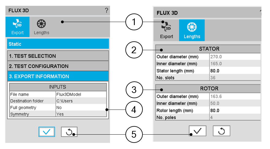
| Motor Factory – EXPORT AREA – Export a model for Flux® 3D | |
| 1 | Tab selector to define general export parameters and axial lengths in Flux® 3D environment |
| 2 | Table containing stator topology features. Stator length may be modified. |
| 3 | Table containing rotor topology features. Rotor length can be modified. |
| 4 |
To reduce computation time in Flux® 3D, full geometry and symmetry options are offered. By default, these options are set to assure minimum computation time without accuracy loss. |
| 5 | Button to validate the previous choices |
Symmetry allows to represent only half of the topology in the axial direction, saving the simulation time. This option is available only when all the dimensions are equal on both sides of the machine (Connection Side and Opposite Connection Side), especially for the end winding dimensions.
A warning message is provided in the “Design environment” each time an asymmetric topology is defined, to inform the user that the Flux® 3D export input “symmetry” has been set to “No”. This also occurs when the asymmetry is due to the end shafts, even if they are not represented in the 3D environment.