Inputs
1. Standard inputs
-
Line current, rms
The line current supplied to the machine: “Line current, rms” ( Line current, rms value ) must be provided.
-
Control angle
Considering the vector diagram shown below, the “ Control angle ” is the angle between the Q-axis and the electrical current (J) (Ψ = (J q , J)).
It is an electrical angle. The default value is 45 degrees. It must be set in a range of -90 to 90 degrees.
This range of values covers all the possible working point in motor convention.
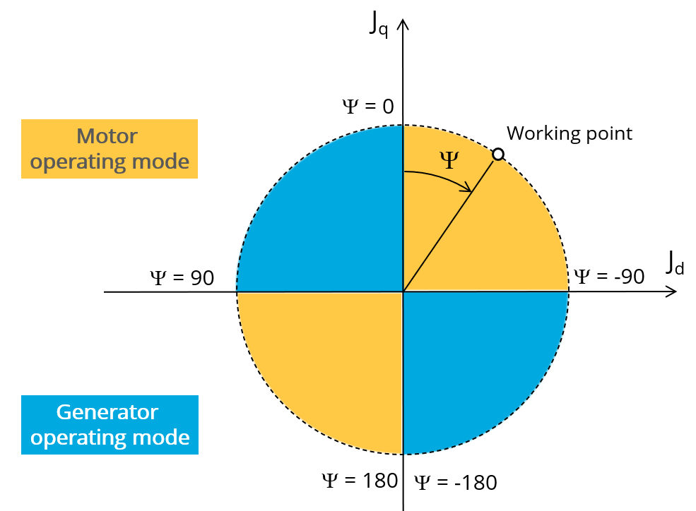
Definition of the control angle Ψ - Motor convention
2. Advanced inputs
The list of advanced inputs dedicated to this export are listed below.
For more details, please refer to the section dedicated to the list of generic advanced inputs.
-
Mesh order
The default level is second order mesh.
-
Airgap mesh coefficient
Airgap mesh coefficient is set to 1.5 by default.
-
Rotor d-axis location
The computations are performed by considering a relative angular position between rotor and stator.
For the reluctance synchronous machines, the rotor d-axis location is defined and automatically used to perform computations.
This value is characterized by the saliency topology. This is important to keep in mind this information it.
For more details, please refer to the document: MotorFactory_2026_SMRSM_IR_3PH_Test_Introduction – section “Rotor and stator relative position”.