SALIENCY
Overview
 |
|
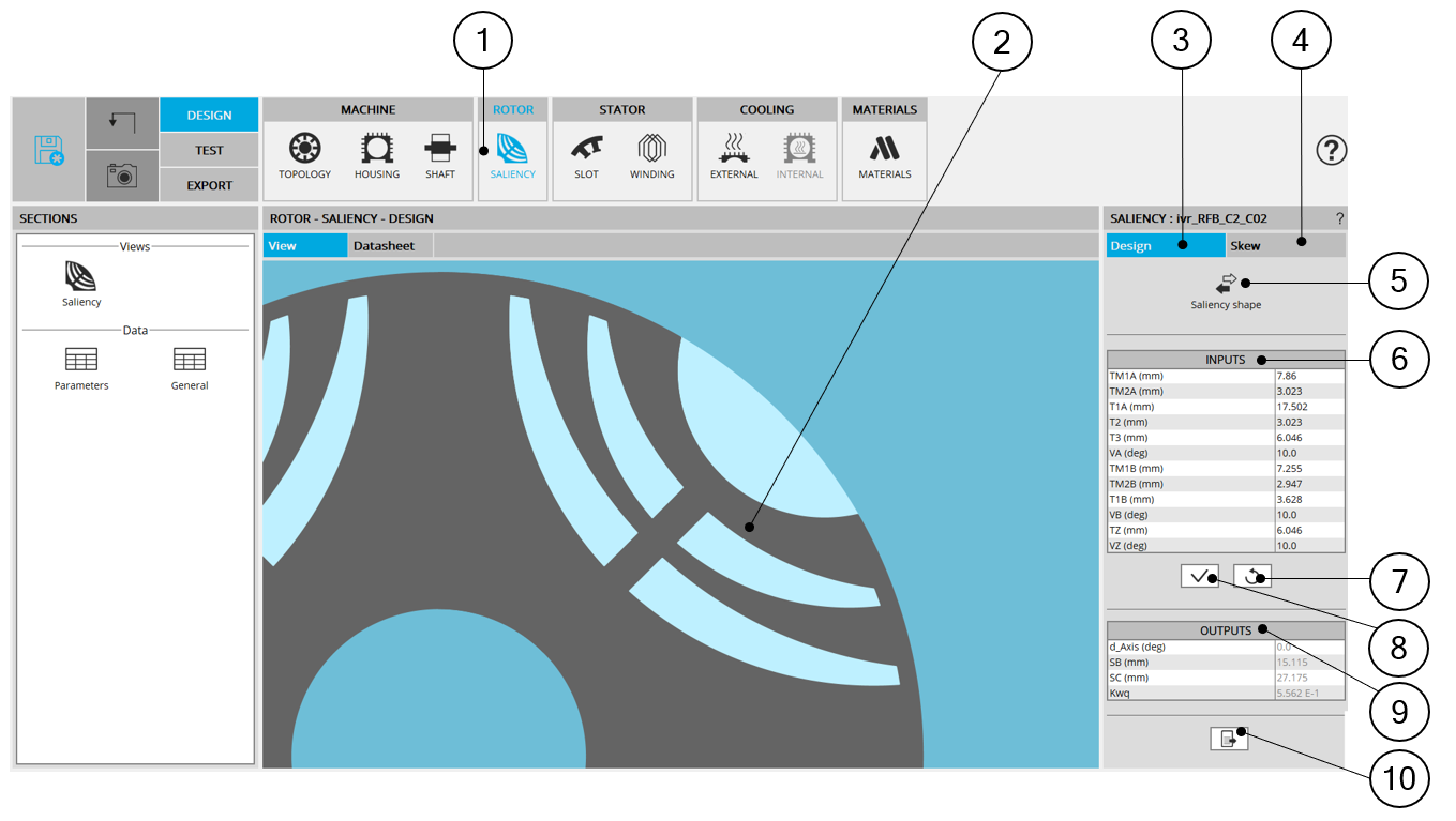
| SALIENCY design area | |
| 1 | Selection of the ROTOR subset: SALIENCY panel (Click on the icon SALIENCY) |
| 2 | Visualization of the motor radial view to view the saliency topology and dimensions. |
| 3 | DESIGN tab indicates the tools to define the saliency topology and
parameter values Note: By default, DESIGN tab is
selected |
| 4 | SKEW tab indicates the tools to define the rotor skew angle |
| 5 | "Saliency shape" button allows accessing the saliency libraries to
change the saliency topology. See additional information below. |
| 6 | User input parameter fields to enter the values. |
| 7 | Button to restore default input values. |
| 8 | Button to apply inputs. Pressing the “enter key” twice applies inputs too. |
| 9 | Output parameters (read only data) to complete the description of the
topology. In this section, the rotor d-axis location is defined and automatically used to perform computations. This value is characterized by the saliency topology.This is important to keep in mind this information it. |
| 10 | Icon to export saliency data into *.txt or *.xlsx files. |