Export to System
Overview
The area SYSTEM, in the EXPORT environment of Motor Factory, allows exporting data like constants, curves and maps in lookup table (LUT) formats, such as FMU and MAT format files.
In the current version, the test Characterization/Model/Maps can be selected for exporting the data.
Constants, curves and maps” given in Jd-Jq plane, for characterizing the 3-Phase synchronous machines with permanent magnets
are computed and exported.
These files can be imported directly into environments like Altair® Activate®, Altair® Compose® or Altair® PSIM® as binary variables files (.mat) or inside block functions, ready to be integrated into schemes to represent the model of the corresponding rotating electrical machine.
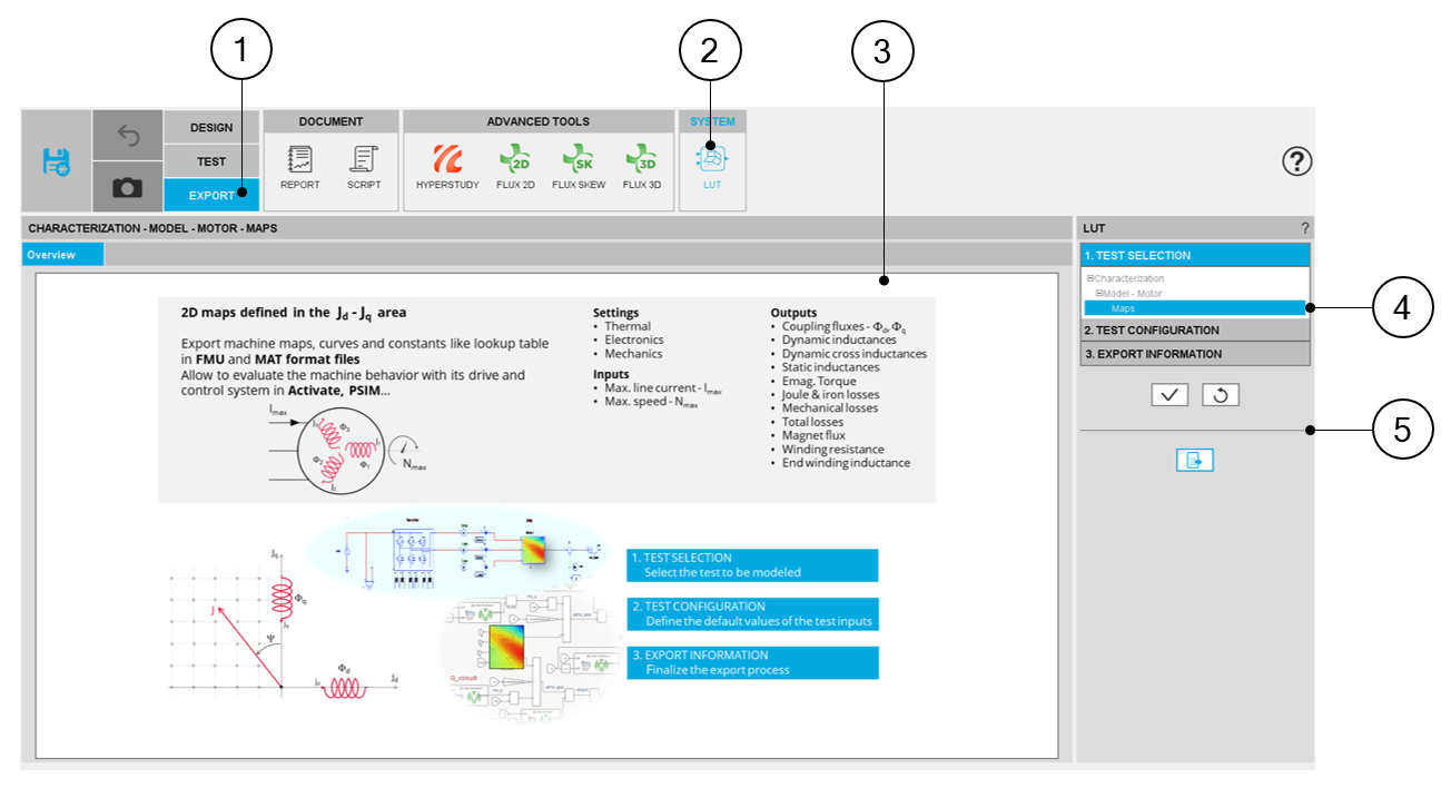
Area to export LUT
 |
|
| Motor Factory – EXPORT AREA – Export data in FMU format files | |
| 1 | Selection of the EXPORT area of Motor Factory. |
| 2 | Access the area (SYSTEM) in which data can be exported in lookup table (LUT) formats. |
| 3 | Zone to visualize either the overview of the selected test |
| 4 | 3 steps to compute and to export LUT data |
| 5 | Button to validate inputs, display a preview and export the data. |
Steps to build an export LUT
Introduction
- Select the test which will be performed for building data to be exported.
- Define the test configuration, that means the user inputs/outputs parameters needed to perform the test (settings and user inputs of the considered test)
- Define the export type (FMU or MAT formats) and information.
Test selection
- Characterization / Model / Motor / Maps
Test configuration
After selecting a test, the corresponding test inputs (settings and user inputs) must be defined. This allows to define the initial conditions for testing.
 |
|
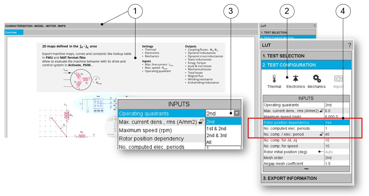
| Motor Factory – EXPORT AREA – SYSTEM – LUT / Test configuration for Characterization / Model / Motor / Maps | |
| 1 | Overview of the selected test is displayed. |
| 2 | User inputs can be defined in the test area. |
| 3 | User’s inputs to export data based on 1, 2 or 4 quadrants |
| 4 | User’s inputs to export data with respect to the rotor position dependency. |
Operating quadrants
Export / System LUT (Activate or PSIM) allows exporting data based on 1, 2 or 4 quadrants
This user’s inputs define the quadrants in the Jd - Jq plane, where the test will be carried out. By default, the only considered quadrant is the 2nd one (i.e., the grid is only defined for negative values of the current in the d axis and positive ones in the q axis). This corresponds to the motor behavior of the machine.
Options allow computing and displaying 1, 2 or 4 quadrants.
By default, the only considered quadrant is the 2nd one (i.e., the grid is only defined for negative values of the current in the d axis and positive ones in the q axis). This corresponds to the motor behavior of the machine.
The other possible values for this input are: “2nd and 3rd “, “1st and 2nd “and “all”.
Rotor position dependency
Export / System LUT (Activate or PSIM) allows exporting data with respect to the rotor position dependency.
This user’s input defines the rotor position dependency, where the test will be carried out. By default, the rotor position dependency is set to “No” but it can be set to “Yes”. In this case the computation will be done in the Jd - Jq plane with an additional third axis corresponding to the rotor position θr.
In case the rotor dependency is set to “Yes”, whatever the operating quadrant choice, the finite element computation is done over all selected quadrants (in case the rotor dependency is set to “No”, symmetries are used).
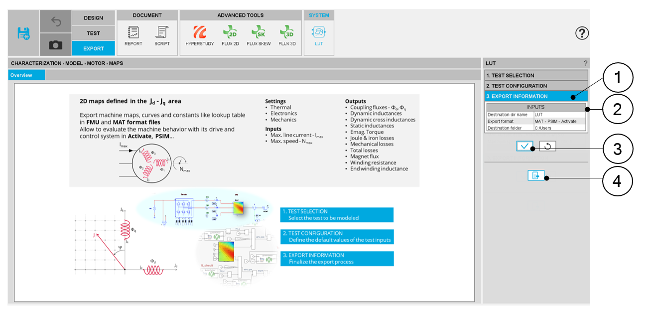
Export information
The last step for building and exporting data in FMU format files is to define the export information.
- The name of the directory in which the created files will be stored
- The format of the file to be exported. Three options are available: FMU for Activate, FMU generic and MAT file - for Acitvate and PSIM.
- The destination folder in which the previous directory will be located.
 |
|
| Motor Factory – EXPORT AREA – SYSTEM – LUT / Export information | |
| 1 | Tab to be expanded to define the export information. |
| 2 | Area in which the export information of parameters to be defined are listed |
| 3 | Button to validate the previous choices |
| 4 | Button to finalize the export of the data files. One click opens the folder where the directory is located |