Model for Flux 3D
Overview
The aim of this export is to provide a python file which allows to get a full parametrized model ready to be used in Altair® Flux® 3D environment.
In the current version of FluxMotor® the only application type available for Flux® 3D export is STATIC for 3-Phase inner rotor SMPM. Export of TRANSIENT application and outer rotor /polyphase machines will be addressed in a future version.
| Application | Model family | Package | Convention | Model / Test |
| STATIC | Without solving scenario | Current source | Motor & Generator | Basic model |
The following section gives a short description of the process to export the model into Flux® 3D environment.
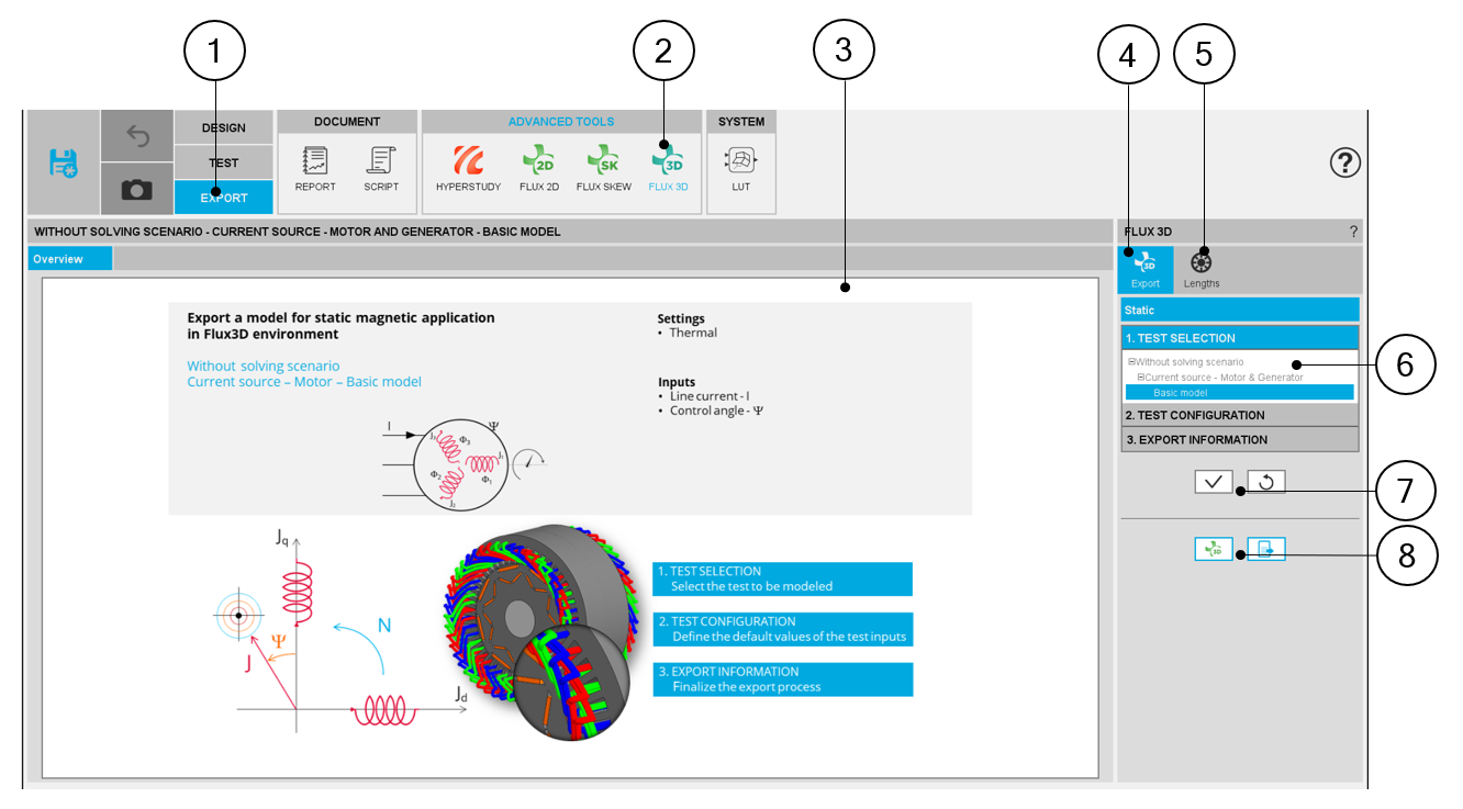
Area to build and to export a model to Flux® 3D environment
 |
|
| Motor Factory – EXPORT AREA – Export model for Flux® 3D environment | |
| 1 | Selection of the EXPORT area of Motor Factory. |
| 2 | Access to the area in which a model for Flux® 3D environment can be made |
| 3 | Zone to visualize the overview of the selected model to be exported |
| 4 | Click on the tab to select the application (in the current version, only STATIC is available) |
| 5 | Different lengths for rotor and stator can be chosen by clicking on this tab. |
| 6 | 3 steps to build the model to be exported for Flux® Skew environment. |
| 7 | Button to validate inputs and export the python file for building the model in Flux® Skew environment. |
| 8 | Buttons to export the python file for building the model in Flux® 3D environment or to launch directly Flux® 3D. |
3. Particularities in building and exporting a model to Flux® 3D environment
A user who wants to build and export a model to Flux® 3D has to follow the same steps and recommendations, as with the function “FLUX 2D”.
The main particularity of function “FLUX 3D” is that rotor and stator axial lengths are the inputs, that must be defined. Their default values equals the machine length defined in “Design”. These two lengths can be different.
 |
|
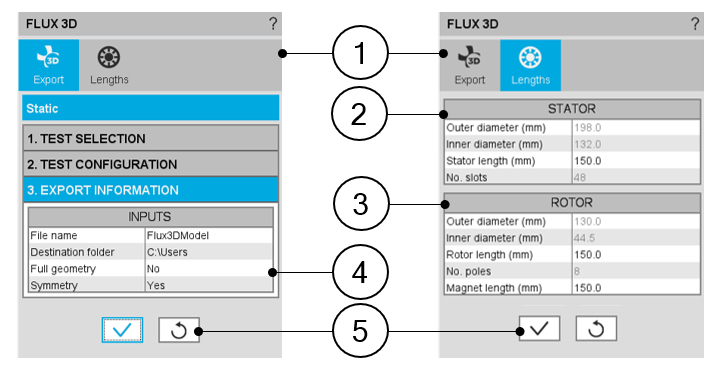
| Motor Factory – EXPORT AREA – Export a model for Flux® 3D | |
| 1 | Tab selector to define general export parameters and axial lengths in Flux® 3D environment |
| 2 | Table containing stator topology features. Stator length may be modified. |
| 3 | Table containing rotor topology features. Rotor and magnets lengths may be modified. |
| 4 |
To reduce computation time in Flux® 3D, full geometry and symmetry options are offered. By default, these options are set to assure minimum computation time without accuracy loss. |
| 5 | Button to validate the previous choices |
Symmetry allows to represent only half of the topology in the axial direction, saving the simulation time. This option is available only when all the dimensions are equal on both sides of the machine (Connection Side and Opposite Connection Side), especially for the end winding dimensions.
A warning message is provided in the “Design environment” each time an asymmetric topology is defined, to inform the user that the Flux® 3D export input “symmetry” has been set to “No”. This also occurs when the asymmetry is due to the end shafts, even if they are not represented in the 3D environment.