Carrier Assignment
Specify the carrier definition settings of a transmitter or cell.
On the Project menu, click Edit Project Parameter and click the Sites tab.
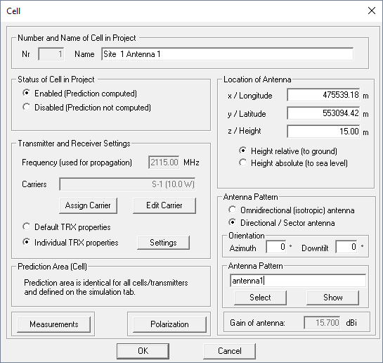
Under Transmitter and Receiver Settings, click Assign Carrier to launch the Carrier Assignment dialog, see Figure 2.
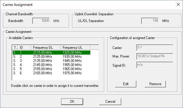
All available carriers are listed under Available Carriers. Double-click on a carrier to assign to the current transmitter. You will see the current transmitter configuration on the right side.
Click Edit to define the individual settings for the selected transmitter/cell, see Figure 3.
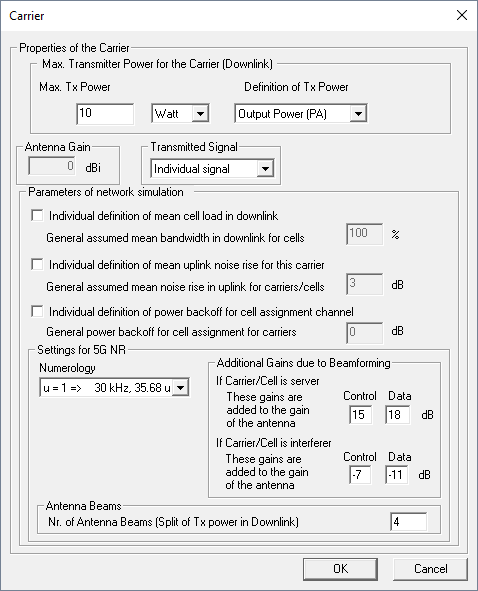
- Maximum Tx Power
- Maximum transmit power of the carrier in dBm or Watt. In case of carrier groups, the specified value applies for each carrier contained in the group.
- Definition of Tx Power
- See transmitter settings.
- Antenna Gain
- Gain of the assigned antenna.
- Transmitted Signal
- This parameter allows the definition of distributed antenna systems (DAS). In DAS
all antennas operating on the same carrier transmit the same signal. Because of
that all received signals from all antennas in the DAS are superposed. Thus the
contributions from the antennas of the DAS are not considered in the calculation
of the interference for this carrier. DAS can be activated by selecting the signal
index in the drop down list
transmitted signal
. The indices (for exampleSignal 1
) of all antennas of the DAS must be the same and all antennas must be on the same carrier of course. Ifindividual signal
is selected in the drop down list, the antenna belongs to no DAS. - MIMO Stream
- In case of a MIMO system, a MIMO stream can be assigned for the carrier.
- Parameters of Network Simulation
-
Mean cell load, mean uplink noise rise and power back off can be defined individually for each transmitter.
- Settings for 5G NT
-
- Numerology
- In 5G, the numerology μ is a key parameter that sets 5G apart from 4G. It governs the sub-carrier spacing and the slot length.
- Additional Gains due to Beamforming
- This parameter enable you to approximate the concept of beam forming by
a 5G phased-array base station antenna. Instead of running a Monte-Carlo
simulation with individual users and beam forming to serve individual
mobile devices, you can simulate with either:
- an omni-directional base station antenna pattern
- an envelope antenna pattern consisting of all possible beams
Both approaches are not complete without specifying additional gains due to beamforming. In case 1, all four fields are available. In case 2, the first two are set to N/A (not applicable) because the gains of the serving beams are already in the envelope pattern. In both approaches, neighboring cells in the simulation produce, with their broader beams, more interference than the real base stations with narrow beams would. The bottom two fields enable you to correct that effect.
- Antenna Beams
- The number of antenna beams also relates to the concept of beamforming by a 5G phased-array base station antenna. Such an antenna might for several beams at once to serve individual mobile devices. This requires the base station to divide its available power over those beams. The number you enter here divides the available power, and the network-planning results are adjusted accordingly.