5G Network Analysis
There are three simulation approaches when analyzing 5G networks.
5G_FDD or 5G_TDD, that triggers a few
small but essential changes. The most important changes are related to simulation
strategies to deal with antenna-pattern information.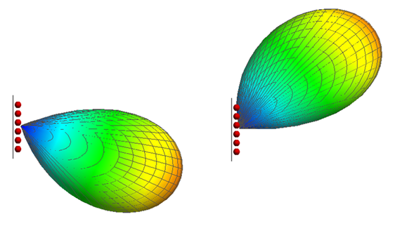
- with isotropic antennas
- with envelope antenna patterns that represent a set of possible beams
- with individual beams
Simulation Based on Isotropic Base-Station Pattern

For a given mobile station, one base station antenna is the server, and the other ones are interferers (if they use the same carrier frequency). The server points its beam to the mobile station, so the expected beam gain to be added to the isotropic antenna is positive. The interferers are serving their own mobile stations and are likely to be pointing their beams in other directions, at least most of the time. Therefore, the gain to be added to those antennas is likely to be small and may be negative.
Simulation Based on Envelope Antenna Pattern
The second possible approach is to simulate with the envelope antenna pattern (see Figure 3) of all possible beams. This assumes that, if a mobile station is in the cell, the base-station array directs its best beam at that mobile station. For that mobile station, the gain of the envelope pattern equals the gain of the specific beam, so the propagation result is correct.

All mobile stations in the same cell receive the best beam for their location, so the envelope pattern provides correct propagation results. Individual mobile stations in the cell may operate on different sub-carriers or be served in different time slots.
For interference from other cells, the gain of the envelope antenna pattern of the interfering cell has to be corrected, because an envelope pattern (in the simulation) will send more power into neighboring cells than one beam (of an actual base station) would. This correction is specified in ProMan during carrier assignment when using an envelope pattern, see Figure 4.

To provide values for additional gain in the interfering case is not hard science. There will be occasional time slots where a narrow beam from an interfering cell points right at a mobile station in a serving cell (correction would be 0 dB, worst case). There will also be more time slots where an interfering beam points in a completely different direction (correction would be -20 dB or lower; only minor interference). The default values of -7 dB and -11 dB are seen as a time average of the occasional worst case and the more-frequent cases where the interfering beam points elsewhere.
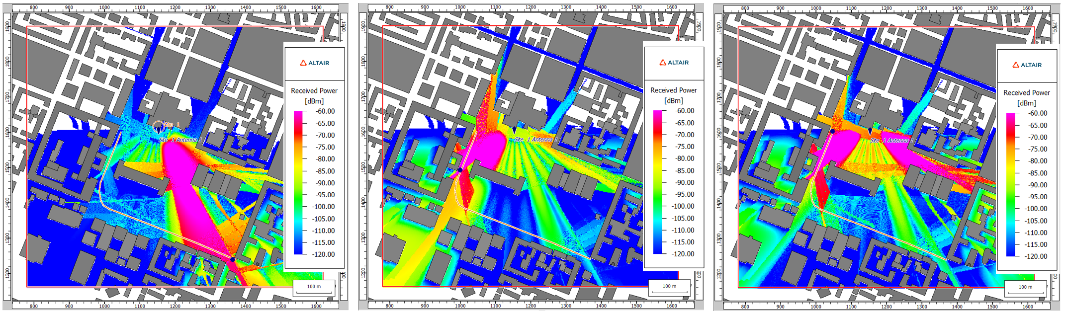
Simulation Based on Individual Beams
The final possible approach is to simulate with individual beams, see Figure 1. Since this requires knowledge of where the mobile stations are, this is usually combined with a Monte-Carlo analysis. When setting up a Monte-Carlo analysis, the offered traffic, which can be location-dependent and service dependent, is specified. During the Monte-Carlo analysis, ProMan generates snapshots with semi-random distributions of mobile stations to be served and performs the network analysis for each snapshot. Since the beams are known, no additional gains due to beamforming need to be specified (contrary to the approaches with omni-directional patterns and with envelope patterns).
Antenna Masking in Network Planning

- Propagation simulation is performed, and results displayed, with an omni-directional (isotropic) pattern.
- Network planning is performed by adjusting propagation results based on actual antenna patterns for control and for data. These could be envelope antenna patterns or individual beams.
The antenna masking feature uses the ray matrix to post-process the propagation paths with each one of the individual beams to compute the power result maps for each beam individually. The best serving beam will be selected accordingly.
- Propagation simulation is performed with one antenna pattern.
- Network planning is based on one antenna pattern for both control and for data.
Masking mode is necessary for Monte Carlo simulations with individual beams, and is useful for simulations with envelope patterns when those for control and for data differ significantly. Traditional mode is attractive for simulations with envelope patterns when the patterns for control and for data do not differ significantly. In the latter case, the display of the propagation results are more informative. In both masking mode and traditional mode, only one propagation simulation per antenna is performed.
Beam Switching Using a Predefined Set of Beams
ProMan supports 5G beam switching capability using a predefined set of beams. Users can be served by a dedicated beam, with the possibility to transition to a different beam as they move.
- Generate the beams, see Beamforming in 5G.
- Select the antenna pattern.
- Click .
- On the Edit Project Parameter dialog, click the Sites tab.
- Add a site and for each site, specify the antenna.
- On the Cell dialog, under the Antenna Pattern group, click Direction / Sector antenna.
- Under Antenna Pattern, browse to the antenna pattern to be used.
- On the Edit Project Parameter dialog, click the
Network tab.
- Under Network Simulation Mode, select the Apply Antenna Masking for Network Planning (Propagation Results with Omni Pattern) check box.
- Define the users.
- Add a stationary or time-variant user point. A user point can also be time-variant and attach to a
defined trajectory.Note:
If no users are defined, all data beams are active.
If users are defined, only the best-serving data beams are active.
- Add a stationary or time-variant user point. A user point can also be time-variant and attach to a
defined trajectory.
- Switch back to the area/rectangle prediction mode.
- Click .
- The data channel results are accessible from the result tree under . Similarly, control channel results are accessible from the result tree under .
- If the user point is time variant, select the time step.
Beam Steering
ProMan supports beam steering in 5G networks, where it dynamically directs radio signals towards specific users, improving signal strength and quality. Beam steering is based on phased array antennas, where the signal phases fed to the antenna elements are adjusted to form a focused beam in the desired direction and can track the movement of users.
- Apply Antenna Masking.
- Click .
- On the Edit Project Parameter dialog, click the Network tab.
- Under Network Simulation Mode, select the Apply Antenna Masking for Network Planning (Propagation Results with Omni Pattern) check box.
- Select the Antenna Array option.
- On the Edit Project Parameter dialog, click the Sites tab.
- Under Sites, add a site.
- On the Cell dialog, under Antenna
Pattern, click Antenna
Array.
Figure 7. The Cell dialog. 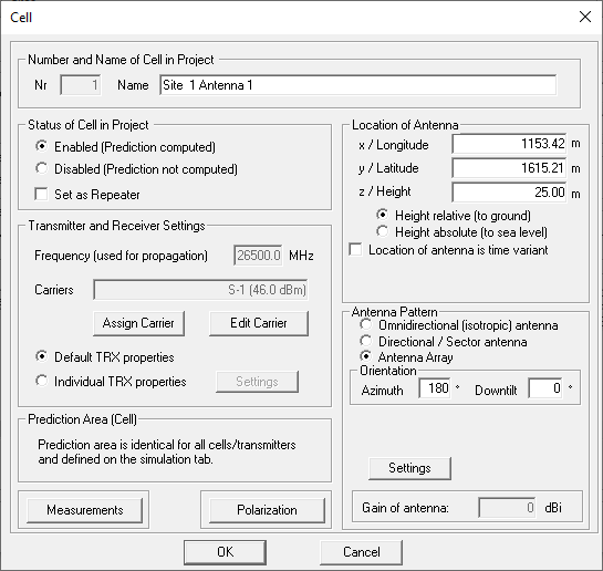
- Under Settings, set up the antenna array
configuration, see Array Tool Options.
Figure 8. The Antenna Array Tool dialog. 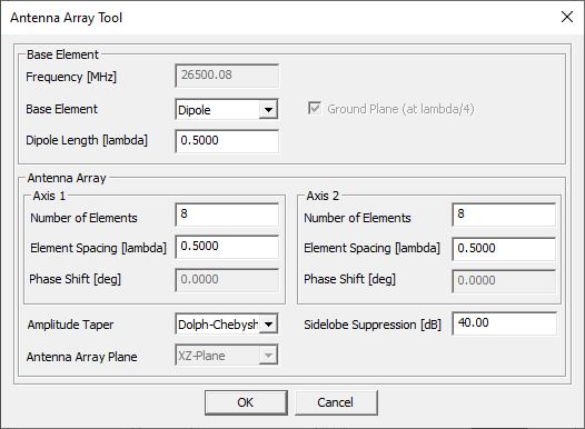
- Define the users.
- Add a stationary or time-variant user point. A user point can also be time-variant and attach to a defined trajectory.
- Switch back to the area/rectangle prediction mode.
- Click .
- The data channel results are accessible from the result tree under . Similarly, control channel results are accessible from the result tree under .
- If the user point is time-variant, select the relevant time step.