Multi-Story Building
Compute indoor propagation in a multi-story building.
Model Type
This is an indoor project featuring a multi-story office building.
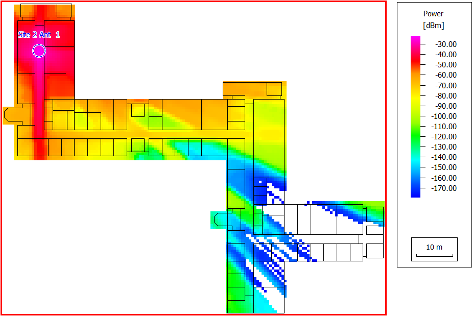
Sites and Antennas
There are two antenna sites at different locations and elevations in the building for the best coverage. Two omnidirectional antennas are placed at two different levels of height, 2.5 m, and 9.95 m. Both antennas use the same carrier frequency of 2 GHz.
Computational Method
To avoid unnecessary computations on floors far from the transmitter, select the Check vertical distance to TRX, Max. allowed vertical distance check box and set to 5 m. Consequently, the results for each antenna are available only for 2 of the 3 prediction heights.
This method performs a rigorous 3d ray tracing prediction resulting in high accuracy while preprocessing reduces the required computation to a large degree.
Results