Tutorial Level: Beginner Add volume expansion/shrinkage to a subcase.
Purpose
SimSolid performs meshless
structural analysis that works on full featured parts and assemblies, is
tolerant of geometric imperfections, and runs in seconds to minutes. In this
tutorial, you will do the following:
Learn how to create volume expansion/shrinkage.
Volume Expansion/Shrinkage is a part level load and has a similar
effect as thermal expansion on the body. Compare 100% volume
expansion to a thermal load of 1 with thermal expansion coefficient
of 1 [1/ ⁰ C].
Model Description
The following model file is needed for this tutorial:
VolumeExpansionShrinkage.ssp
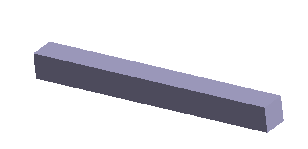
Figure 1.
The file has the following specifications:
Material is set to 'Steel Temp Coeff 1' for all parts.
Linear static analysis with thermal load of 1 degree C with results.
You will use these results as a reference for the subcase with
volume expansion/shrinkage.
Open Project
Start a new SimSolid session.
On the main window toolbar, click Open Project.
In the Open project file dialog, choose
VolumeExpansionShrinkage.ssp
Click OK.
Review Model
Review the Steel Temp Coeff 1 material property.
In the Project Tree, right click
Assembly and select Show > Materials > Properties.
Thermal expansion coefficient is set to 1 [1/degree C].
Close material review dialogs.
In the Project Tree, review the boundary
conditions.
Only lengthwise expansion is permitted.
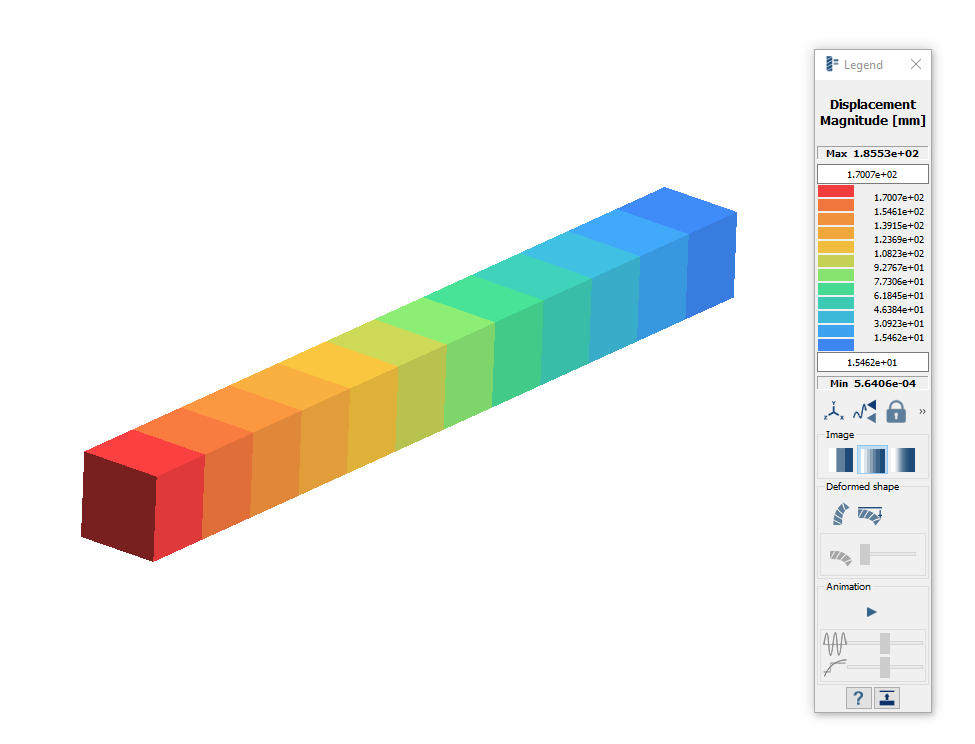
Plot the displacement magnitude.
In the Project Tree, click the
Results branch.
On the Analysis Workbench, select > Displacement Magnitude.
Figure 2.
Copy Analysis
In the Project Tree, right-click on
Structural 1.
Choose Copy from the context menu.
The Structural 2 analysis appears in the Project Tree.
In Structural 2, expand the Loads&Constraints
branch.
Right-click on Thermal load and choose
Delete in the context menu.
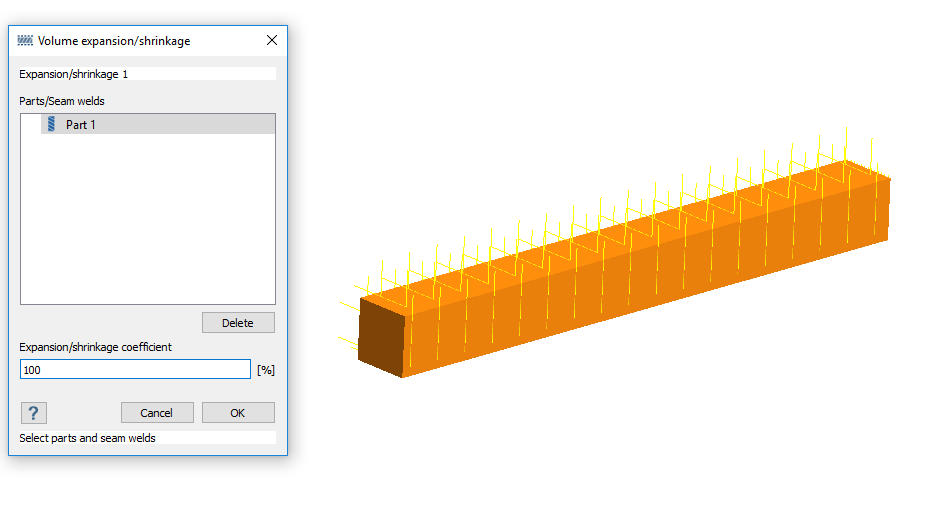
Create Volume Expansion
On the Analysis Workbench toolbar, select (Volume expansion/shrinkage).
In the modeling window, select Part
1 (the only part in the model).
The part is shown in orange in Figure 3. You can apply expansion/shrinkage to parts and seam
welds.Figure 3.
In the dialog, for Expansion/shrinkage coefficient, enter
100.
Click OK.
Run Analysis
On the Project Tree, open
the Analysis Workbench.
Click Solve.
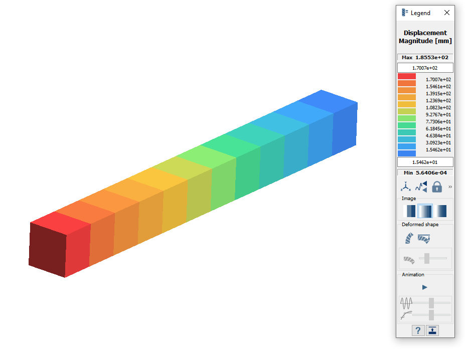
Review Results
On the Analysis Workbench, select > Displacement Magnitude.
The Legend window opens and displays the contour
plot. You can click between the results for Structural 1 and Structural 2 to
compare.Figure 4.
 .
.
 > Displacement Magnitude.
 (Volume expansion/shrinkage).
 Solve.