SS-T: 3030 Distributed Mass
Apply distributed mass in SimSolid.
- Purpose
- SimSolid performs meshless structural
analysis that works on full featured parts and assemblies, is tolerant of
geometric imperfections, and runs in seconds to minutes. In this tutorial,
you will do the following:
- Learn how to apply distributed mass by total area or mass per area.
- Model Description
-
The following model file is needed for this tutorial:
- DistributedMass.ssp
-
Figure 1. 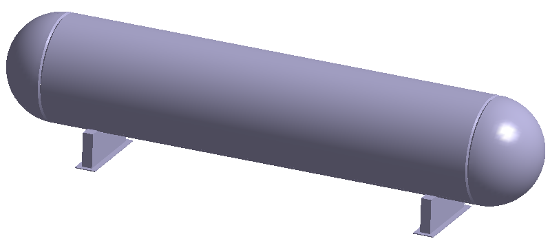
Open Project
- Start a new SimSolid session.
-
On the main window toolbar, click Open Project
 .
.
- In the Open project file dialog, choose DistributedMass.ssp
- Click OK.
Option 1: Apply Distributed Mass by Total Mass
This is one of two methods for applying distributed mass. To instead apply using mass per area, see Option 2: Apply Distributed Mass by Mass Per Area.
-
On the main window toolbar, select
 (Clip assembly with plane).
You can now see the inner faces of the vessel.
(Clip assembly with plane).
You can now see the inner faces of the vessel. - In the Project Tree, click on the Modal 1 modal analysis branch.
-
On the Analysis Workbench, click
 (Distributed Mass).
-
Select the inner faces of the vessel as shown in orange in Figure 2.
Figure 2. 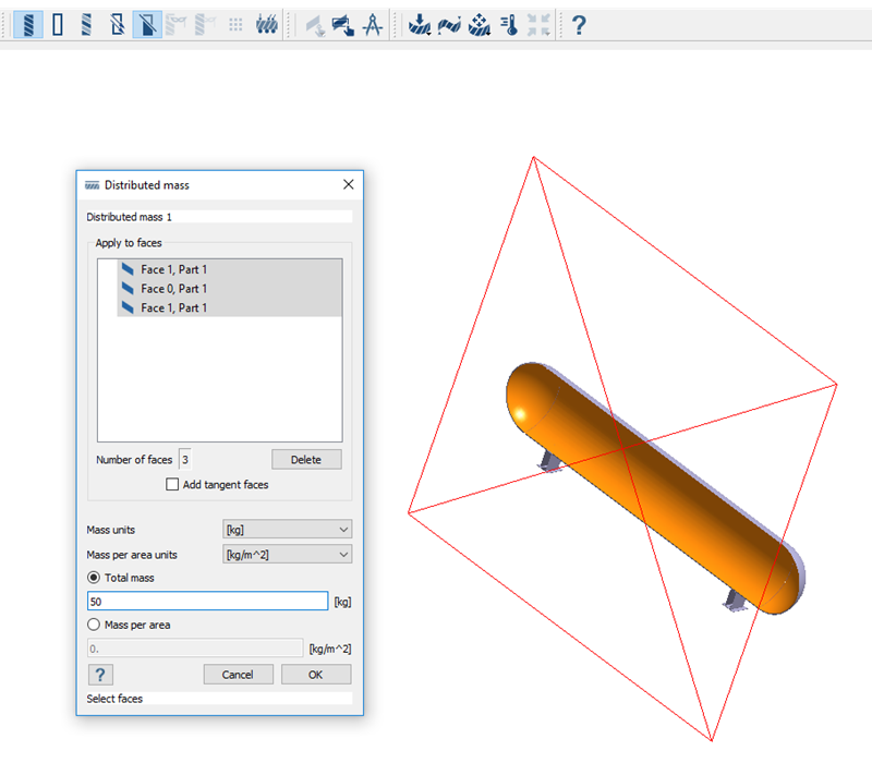
-
Set Total mass.
- In the Distributed mass dialog, select the Total mass radio button.
- In the text box, enter 50.
- Click OK.
Option 2: Apply Distributed Mass by Mass Per Area
This is one of two methods for applying distributed mass. To instead apply using total mass, see Option 1: Apply Distributed Mass by Total Mass.
-
On the main window toolbar, select
(Clip assembly with plane).
You can now see the inner faces of the vessel.
- In the Project Tree, click on the Modal 1 modal analysis branch.
-
On the Analysis Workbench, click (Distributed Mass).
-
Select the inner faces of the vessel as shown in orange in Figure 2.
Figure 3. 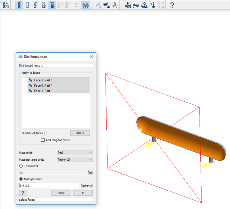
-
Set Mass per area.
- In the Distributed mass dialog, select the Mass per area radio button.
- In the text box, enter 8.6173.
- Click OK.
Run Analysis
- On the Project Tree, open the Analysis Workbench.
-
Click
 (Solve).
Review Results
-
On the Analysis Workbench
toolbar, click
 (Results plot).
-
Select Displacement Magnitude.
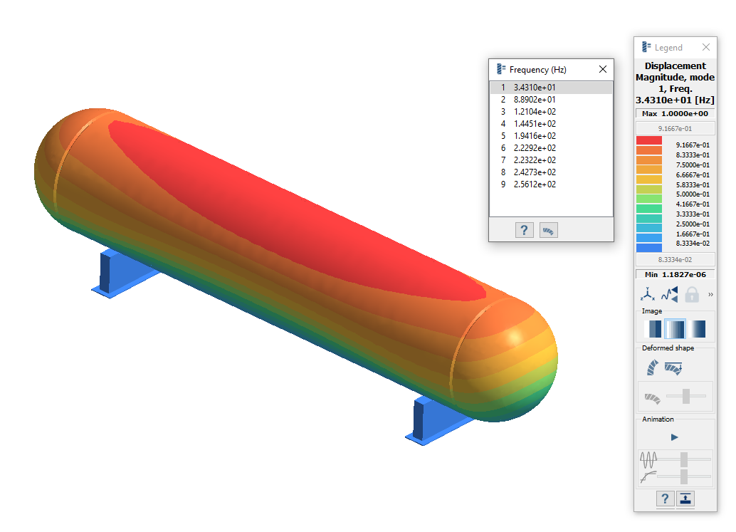
The Legend window opens and displays the contour plot. The Frequency (Hz) window opens and displays the modes.
Figure 4. 
Compare Results With and Without Distributed Mass
-
Create a second modal analysis.
-
Remove distributed mass from Modal 2.
- In the Project Tree, expand the Modal 2 branch.
- Under Constraints, right-click on Distributed mass 1 and choose Delete from the context menu.
-
Solve Modal 2.
- In the Project Tree, ensure Modal 2 is selected.
-
On the Analysis Workbench, click
 (Solve).
The Results branch appears under the Modal 2 branch in the Project Tree. -
Plot Displacement Magnitude for Modal 2.
-
On the Analysis Workbench
toolbar, click (Results plot).
- Select Displacement Magnitude.
-
On the Analysis Workbench
toolbar, click
-
In the Project Tree, click between the
Results branches for Modal 1 and Modal 2 to compare
the Displacement Magnitude plots.
Figure 5. Results with Distributed Mass
Figure 6. Results without Distributed Mass