SS-T: 3000 Non-linear Separating Contact and Bolt Pretensioning, Hanger Beam
Perform non-linear separating contact analysis and setup bolt/nut tightening loads.
- Prerequisites
- Some features used in this tutorial are only available in SimSolid Advanced version. Please switch to Advanced to complete this tutorial.
- Purpose
- SimSolid performs meshless structural
analysis that works on full featured parts and assemblies, is tolerant of
geometric imperfections, and runs in seconds to minutes. In this tutorial,
you will do the following:
- Perform assembly analysis
- Perform non-linear separating contact analysis
- Use SimSolid bolt tensioning functions
- Compare SimSolid results with those obtained in traditional FEA.
- Model Description
- The hanger beam model in this tutorial has 70 parts, 16 bolts/nuts, and 32 washers.
-
Figure 1. 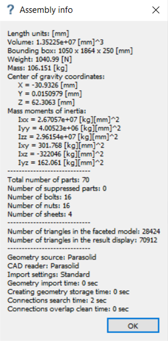
Open Project
- Start a new SimSolid session.
-
On the main window toolbar, click Open Project
 .
.
- In the Open project file dialog, choose Hanger Beam.ssp
- Click OK.
Create Non-linear Separating Contact Analysis
-
In the Project Tree, right-click Structural
1 and choose Copy.
The copy will appear as Structural 2 in the Project Tree.
- Under Structural 2, right-click on Setup and choose Edit.
-
In the dialog, select the Separating contact check
box.
Figure 2. 
- Click OK.
Edit Contact Conditions
-
In the Bookmark browser, click Bookmark 5.
Figure 3. 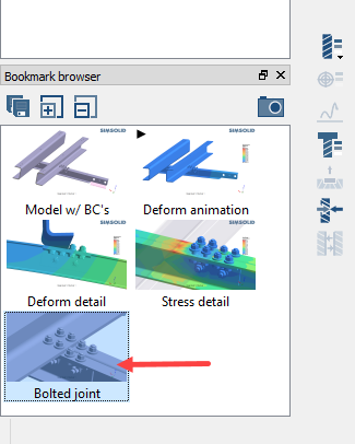
The modeling window updates with the saved view. -
In the modeling window, right-click on the
Hanger beam (shown in orange) and select
Review part contact conditions.
Figure 4. 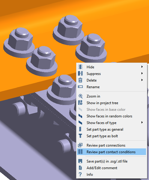
- In the dialog, hold down Control and click to select Connection 120 and Connection 121.
-
Click the Edit contact conditions button.
Figure 5. 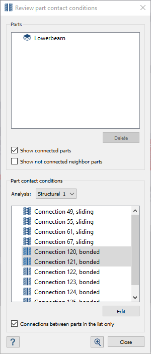
- In the Contact conditions dialog, select Structural 2.
-
Activate the Separating radio button.
Figure 6. 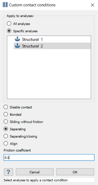
- For the Friction coefficient, specify 0.1.
- Click OK.
Run Analysis
- On the Project Tree, open the Analysis Workbench.
-
Click
 (Solve).
Compare Results
- In the Project Tree, select the Structural 1 branch.
-
In the Bookmark browser, choose Bookmark 3.
This bookmark shows the deformation detail.
Figure 7. 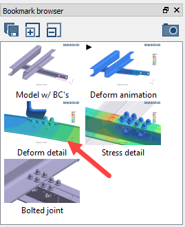
-
In the Project Tree, select the Structural
2 branch.
The modeling window updates to show deformation detail for Structural 2.
- Optional: Switch back and forth between Analysis branches to highlight the differences in the results.
-
Repeat steps 1
through 4 for
Bookmark 4 (stress detail).
Figure 8. 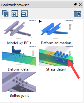
View Separation and Contact Forces
- In the Project Tree, select the Results branch under Structural 2.
-
On the Analysis Workbench, select
 (Contact Response).
Figure 9. 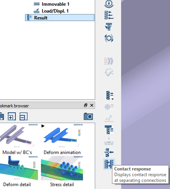
- In the Response at connections dialog, hold down Control and click to select Connection 120 and Connection 121.
- Select the response type you wish to view.
-
Use the slider to increase or decrease the size of the colored points.
Figure 10. 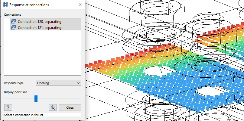
- Click Close.
Setup Bolt/Nut Tightening
-
In the Project Tree, right-click on
Structural 2 and select
Copy.
The copy appears as Structural 3 in the Project Tree.
- In the Bookmark browser, select Bookmark 5 (Bolted joint).
- Verify Structural 3 is selected in the Project Tree.
-
In the Analysis Workbench toolbar, click
 (Bolt/nut tightening) .
-
In the modeling window, select the 4 nuts attached to
the hanger beam as shown in Figure 11.
Figure 11. 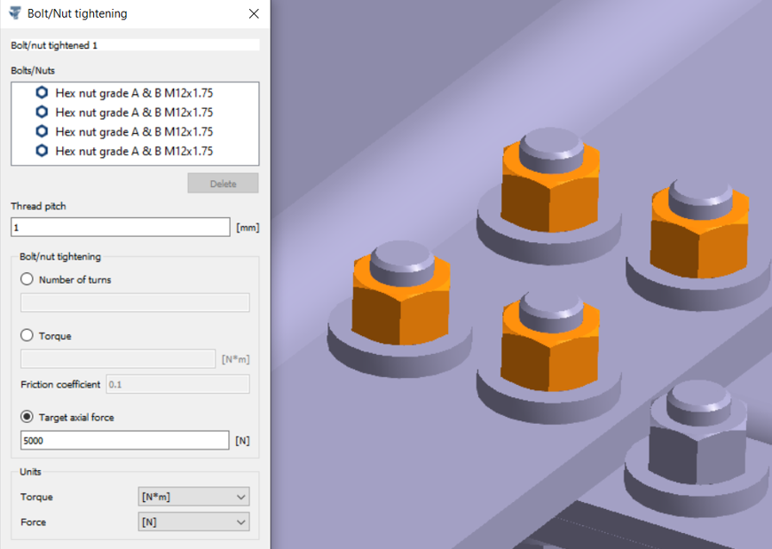
- For Thread pitch, enter 1 mm.
- Activate the Target axial load radio button and enter 5000 N.
- Click OK.
Run Analysis
- On the Project Tree, open the Analysis Workbench.
-
Click (Solve).
Compare Results
- In the Project Tree, select the Structural 1 branch.
-
In the Bookmark browser, choose Bookmark 3.
This bookmark shows the deformation detail.
Figure 12.
-
In the Project Tree, select the Structural
2 branch.
The modeling window updates to show deformation detail for Structural 2.
- Optional: Switch back and forth between Analysis branches to highlight the differences in the results.
-
Repeat steps 1
through 4 for
Bookmark 4 (stress detail).
Figure 13.
Compare with Traditional FEA
-
Use the model files to run this same analysis with your traditional FEA
application.
Important:
- Do not merge or simplify geometry, use bonded and sliding contact same as SimSolid.
- Check for part overlaps
- Make sure element density is acceptable for smaller parts
-
Compare the following between the two programs:
- Solution quality
- Number of workflow steps required
- Time required to mesh
- Time required to solve
- Time required to examine results
- Time required to refine and rerun model