SS-T: 1060 Local Coordinate Systems (LCS)
SimSolid allows resolving boundary conditions and virtual connections along a local coordinate system. Querying results in local coordinate system is also supported.
- Purpose
- SimSolid performs meshless structural
analysis that works on full featured parts and assemblies, is tolerant of
geometric imperfections, and runs in seconds to minutes. In this tutorial,
you will do the following:
- Create local coordinate system for a pull-up bar.
- Model Description
- The following model file is needed for this tutorial:
- Pullup_bar_V1.ssp
Open Project
- Start a new SimSolid session.
-
On the main window toolbar, click Open Project
 .
.
- In the Open project file dialog, choose Pullup_bar_V1.ssp
- Click OK.
Review Model
- In the Project Tree, expand Structural 1.
- Expand the Loads&Constraints branch and review the immovable support created at the brackets.
Create LCS
-
Select the assembly on the Project Tree, and click
 .
Tip: Coordinates systems can be created manually or by importing a .csv.
.
Tip: Coordinates systems can be created manually or by importing a .csv. -
Click Create co-ordinate system.
The LCS dialog opens.
-
Set User selection mode to Set as COG of selected faces,
and then select the face highlighted in orange.
You can set the origin by entering the X, Y, and Z coordinates or by clicking a point in the modeling window. Selection in the modeling window when User selection mode is set to Set as COG of selected faces, places the origin at the center of the selected face. User selection mode set to Pick on part puts the origin at the selected point.
Figure 1. 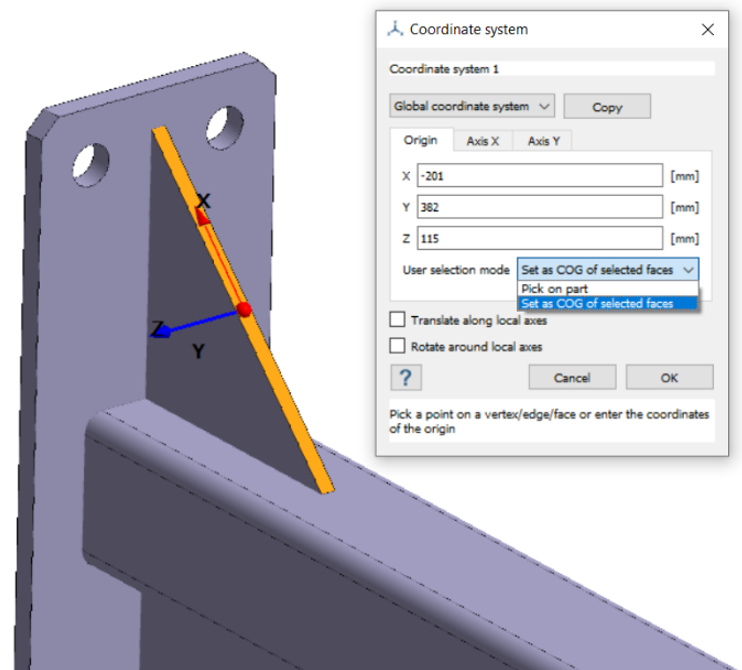
-
Open the Axis X tab, and then select the edge highlighted in pink.
This orients the X-axis along the selected edge.
Figure 2. 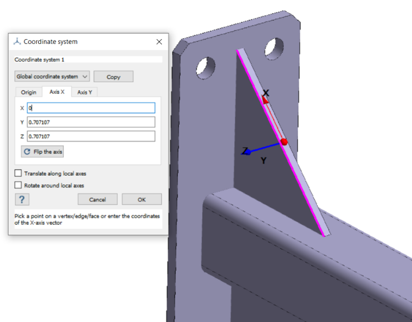
Note:- Direction vectors for each axis can be defined manually or can be set by selecting a vertex/edge/face.
- Translate and rotate along local axes options can be used to translate and rotate the axes.
- Click OK.
Apply Load
-
In the Structural 1 workbench, click
 .
.
- In the Force/Displacement dialog, select the Faces radio button.
-
In the modeling window, select the faces highlighted in
orange.
Figure 3. 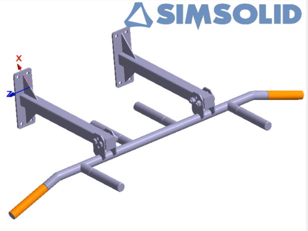
- Set the Coordinate system to Coordinate system 1 from the dropdown.
- For Total force or displacement along the axes, enter -1500 [N] for the X-axis.
- Click OK.
- Optional:
On the main toolbar, click
 to see the
location and direction of the applied load.
to see the
location and direction of the applied load.
Figure 4. 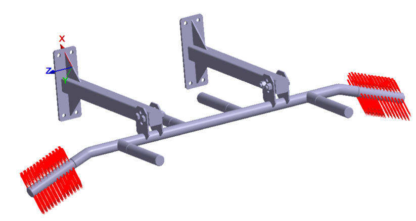
Run Analysis
- On the Project Tree, open the Analysis Workbench.
-
Click
 (Solve).
Review Results
- In the Project Tree, select Structural 1.
-
On the Results Workbench, select
 > Displacement X.
The legend window appears and the modeling window displays the contour plot.
> Displacement X.
The legend window appears and the modeling window displays the contour plot. -
In the legend window, click .
- In the dialog, select Coordinate system 1 from the dropdown.
- Set the type to Cartesian.
- Click OK to plot the contour with respect to the local coordinate system.
- Close the contour plot.
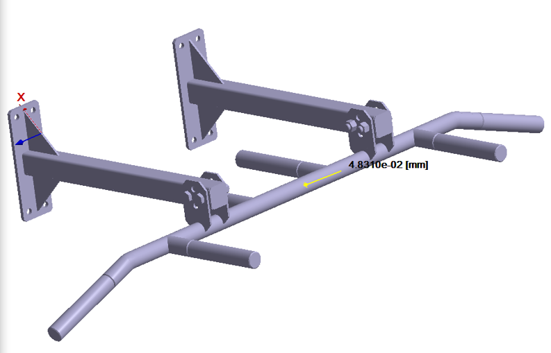
-
Click Pick Info
 .
.
- In the Pick Info dialog, set Response to Displacement X.
- For Coordinate system, select Coordinate system 1 from the dropdown.
- Select a point in the modeling window to view the results along the local coordinate system.