SimSolid performs meshless structural
analysis that works on full featured parts and assemblies, is tolerant of
geometric imperfections, and runs in seconds to minutes. In this tutorial,
you will do the following:
Apply liquid body to a water tank.
Model Description
The following model file is needed for this tutorial:
LiquidMass.ssp
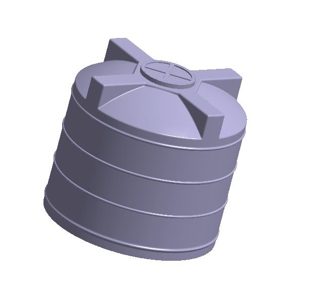
Figure 1.
This file has the following specifications:
Material is set to Plastic for all parts.
Regular connections with 2mm gap and penetration tolerance.
Modal analysis defined and solved.
Open Project
Start a new SimSolid session.
On the main window toolbar, click Open Project.
In the Open project file dialog, choose
LiquidMass.ssp
Click OK.
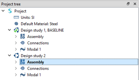
Copy Design Study
In the Project Tree, right-click the Design
study 1, BASELINE branch and select Copy
from the context menu.
Design study 2 will appear in the Project Tree.
You will apply liquid body to the second design study.Figure 2.
Apply Liquid Body
In the Project Tree, click on the
Assembly branch.
On the workbench toolbar, select .
On the main window toolbar, select
(Clip assembly with plane).
This will allow you to select the inner faces of the water
tank.
In the modeling window, select faces as shown in orange
in Figure 3.
Figure 3.
For Total mass, enter 10.
Click OK.
Run Analysis
On the Project Tree, open
the Analysis Workbench.
Click (Solve).
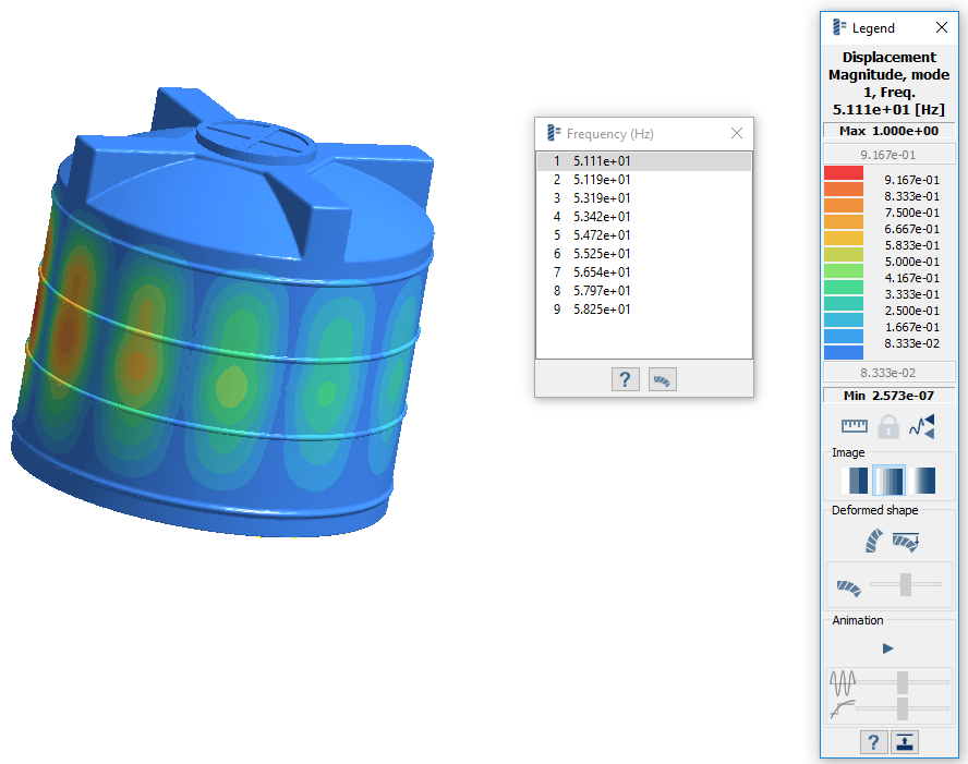
Review Results
In the Project Tree, select Design Study 1 > Modal 1 subcase.
On the Analysis Workbench, select > Displacement Magnitude.
The Legend window will open and display the contour
plot. The Frequency (Hz) window will open and list the
modes.Figure 4.
Compare Results With and Without Liquid Body
Plot Displacement Magnitude for the Modal 1 subcase of Design Study 1.
On the Project Tree, select Design Study 1 > Modal 1.
On the Analysis Workbench
toolbar, click (Results plot).
Select Displacement Magnitude.
In the Project Tree, click between the
Results branches for Modal 1 from both Design Study 1
and Design Study 2 to compare the Displacement magnitude plots.
Figure 5. Results with Liquid Body Figure 6. Results without Liquid Body
 .
.
 .
.
 (Clip assembly with plane).
This will allow you to select the inner faces of the water tank.
(Clip assembly with plane).
This will allow you to select the inner faces of the water tank.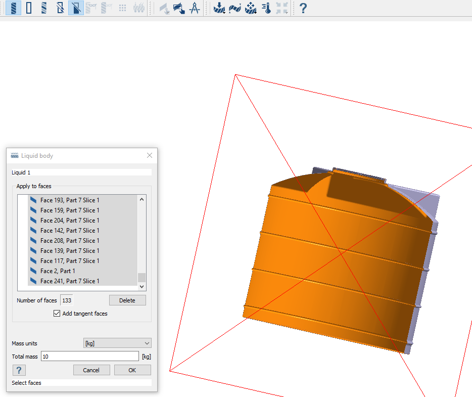
 (Solve).
 > Displacement Magnitude.
The Legend window will open and display the contour plot. The Frequency (Hz) window will open and list the modes.
> Displacement Magnitude.
The Legend window will open and display the contour plot. The Frequency (Hz) window will open and list the modes.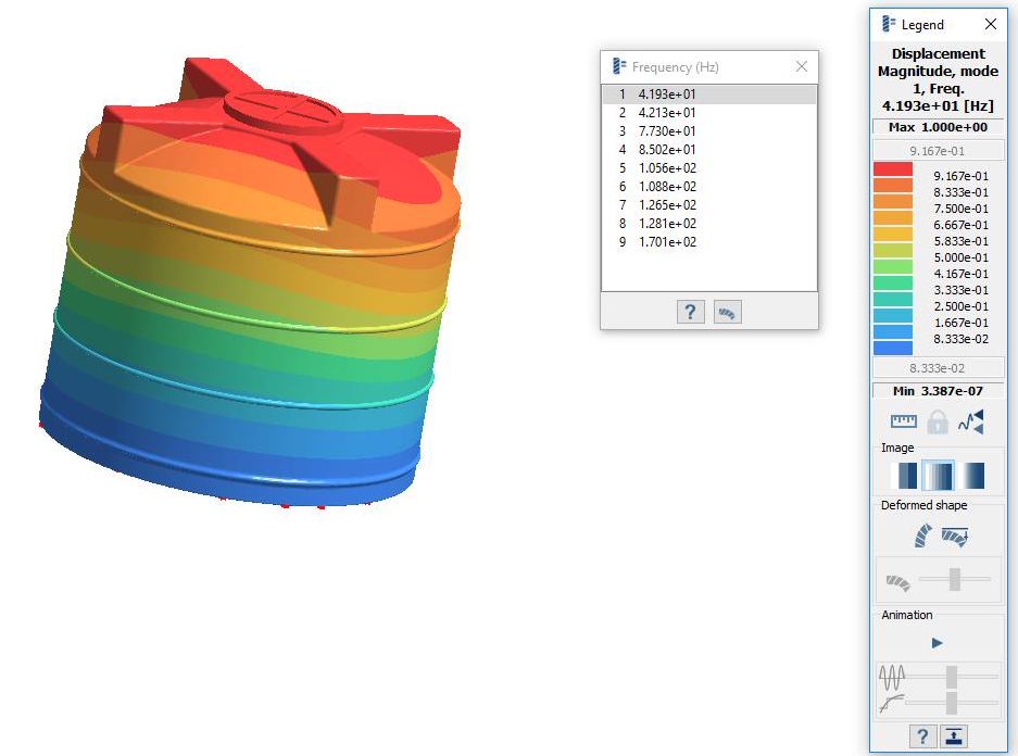
 (Results plot).