SS-T: 1055 Part Replacement
Tutorial Level: Beginner Replace a part in an existing assembly with an alternative design.
- Purpose
- SimSolid performs meshless
structural analysis that works on full featured parts and assemblies, is
tolerant of geometric imperfections, and runs in seconds to minutes. In this
tutorial, you will do the following:
- Learn how to replace parts in the assembly.
- Model Description
- The following model file is needed for this tutorial:
- Sub-frameV1.x_t
- side_bracket.x_b
Import Geometry
- Open a new SimSolid session.
-
Click
 Import from file .
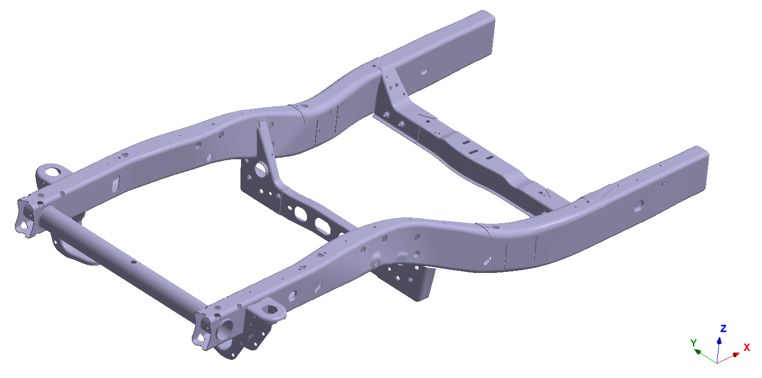
- In the Open geometry files dialog, choose Sub-frameV1.x_t.
-
Click Open.
The assembly will load in the modeling window.
- The Automatic connections dialog opens. Click Cancel to close.
Assign Materials
- In the Project Tree, open the Assembly workbench.
-
In the Assembly workbench, select
 Apply/review
materials > Apply materials.
Apply/review
materials > Apply materials.
- Select Steel from the Generic materials list.
- Click Apply to all parts.
-
Click Close.
In the Assembly branch of the Project Tree, material properties are identified for each part.
Create Seam Welds from Solids
- In the Project Tree, open the Connections workbench.
-
In the Connections workbench toolbar, select
 Seam
welds > Create new seam welds.
Seam
welds > Create new seam welds.
- In the Create seam welds dialog, select the Find parts by keyword radio button.
-
Enter Weld and click Find
parts.
In the dialog, a preview of the found welds is shown.
Figure 2. 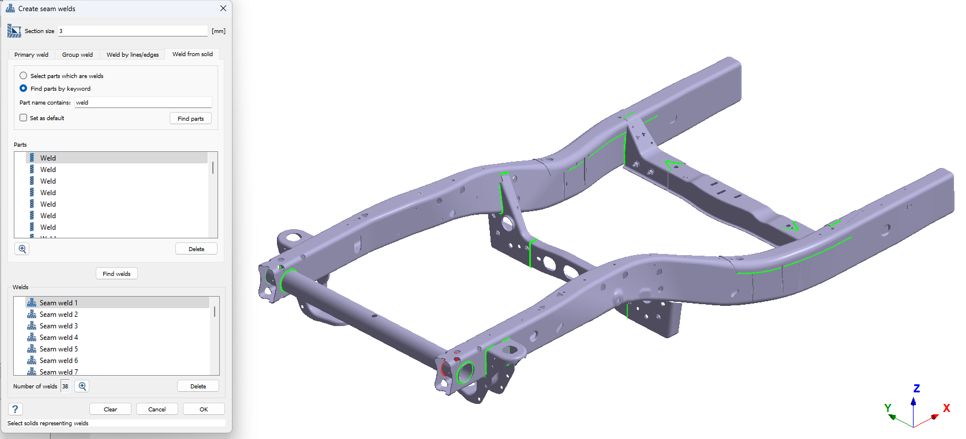
- Click OK.
Create Regular Connections
-
In the Connections workbench, click
 Automatic connections.
- In the Automatic connections dialog, keep the default Gap and Penetration values.
- Select the Connect unwelded parts only checkbox. This restricts the connection search to areas that were not previously welded.
- Click OK.
Create Structural Linear Analysis
In the main window toolbar, click  Structural >
 Structural
linear.
Structural
linear.
The new analysis appears in the Project Tree
under Design study 1 and the Analysis Workbench
opens.
Create Immovable Support
-
In the Analysis Workbench, select
 Constraints > Immovable support.
- In the dialog, verify the Faces radio button is selected.
-
In the modeling window, select the face(s) highlighted in
orange in the figure below.
Figure 3. 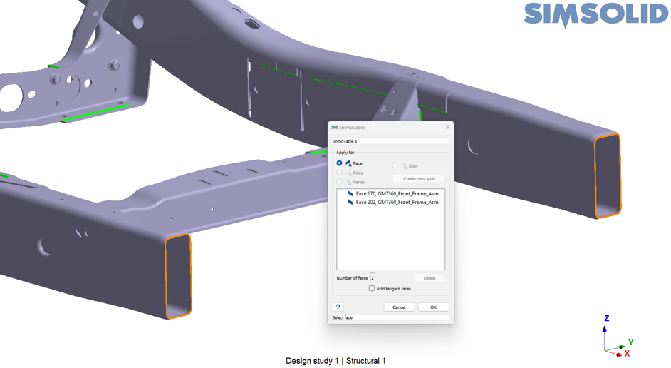
-
Click
OK.
The new constraint, Immovable 1, appears in the Project Tree. A visual representation of the constraint is shown on the model.
Create Remote Load
-
In the Analysis Workbench, select
 Remote
loads.
Remote
loads.
- In the dialog, verify the Faces radio button is selected.
-
In the modeling window, select the internal faces of
the bracket highlighted in orange in the figure below.
Figure 4. 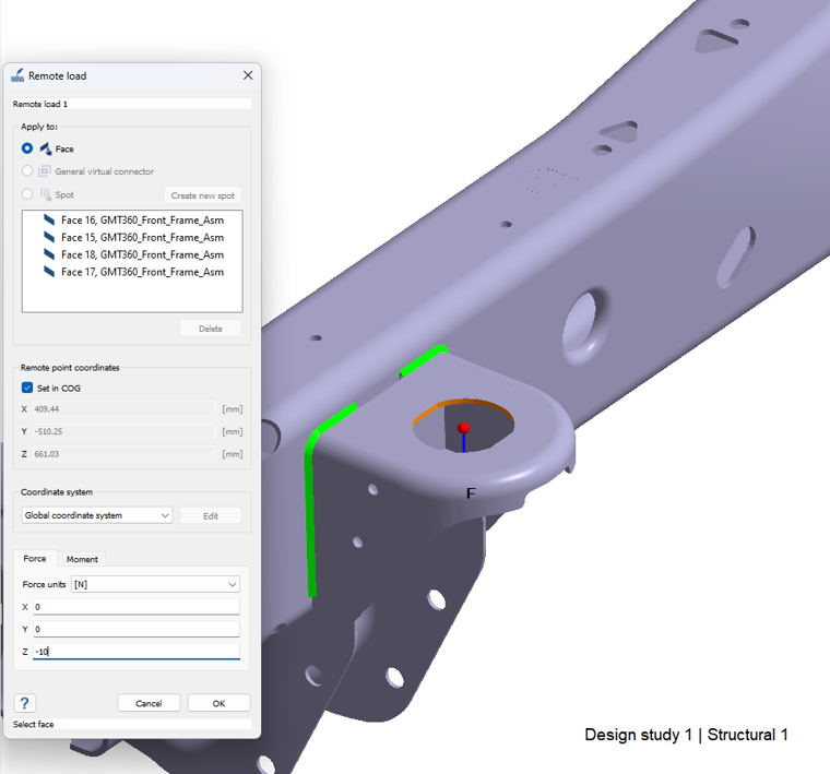
- In the Force tab, enter a value of -10 N in the Z direction.
- Click OK.
Replace the Bracket
-
Right-click on the part from the Project Tree or
modeling window that will be replaced, and then
click
 Replace
part.
Replace
part.
Figure 5. 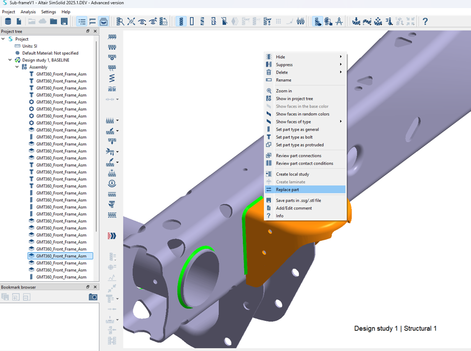
-
Select the part file, side_bracket.x_b, from the File
Explorer and click Open.
After opening the new part, a new design study will be created with the replaced part.
Figure 6. 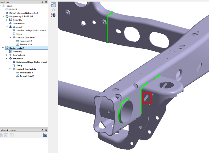
Note: In the red square in the figure above, there is a cutout in the bracket in Design study 2.
Review Design Study 2
-
In the Project Tree, expand
Assembly and
Connections.
The material has been carried over for the new part, and the regular and seam weld connections have been carried over from the previous Design Study 1. Loads and constraints have also been carried over from Design study 1. This design change is intended to reduce the overall weight of the chassis without changing the stiffness of the bracket.
-
In the Project Tree, right-click on the replaced part
in Design study 2 and then select Info to view the mass
of the part.
Figure 7. 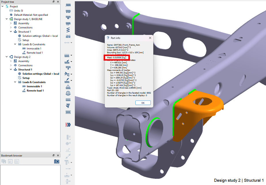
-
Repeat the same for Design study 1.
Figure 8. 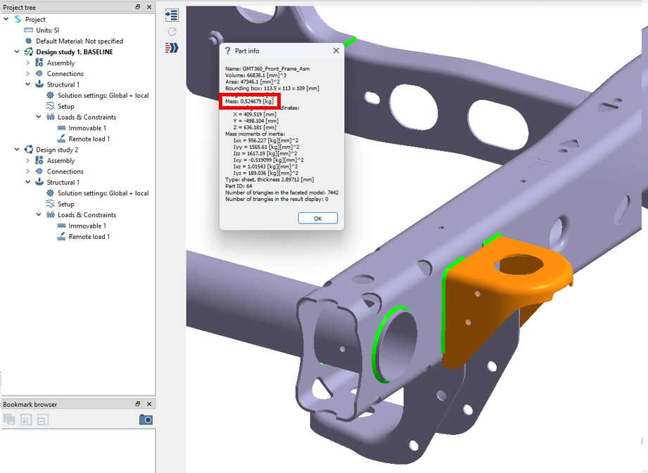
Notice the difference in bracket weight in Design Study 2, 0.515 kg, compared to Design study 1, 0.524 kg.