SS-T: 1076 Curved Composites
Tutorial Level: Intermediate
- Purpose
- SimSolid performs meshless
structural analysis that works on full featured parts and assemblies, is
tolerant of geometric imperfections, and runs in seconds to minutes. In this
tutorial, you will do the following:
- Learn how to create laminates for curved and protruded geometries in
SimSolidNote: Version 2025.1 supports laminates with orthotropic material for flat, curved and revolved parts.
- Learn how to create laminates for curved and protruded geometries in
SimSolid
- Model Description
- The following model file is needed for this tutorial:
- Fuselage.x_b
Figure 1 shows the fuselage model used for this tutorial. The stringers and the skin of the fuselage are imported as CAD surfaces, whereas the frames are imported as solid sheets. In this tutorial, you will create laminates for the curved skin and the protruded stringers.
Figure 1. 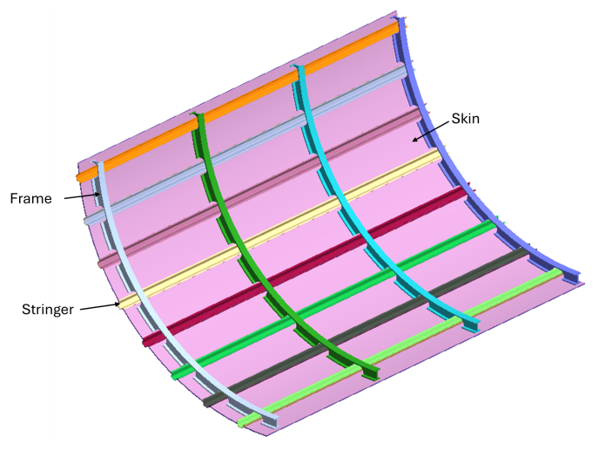
Activate Import Solids and skins
- Launch a new SimSolid session.
- In the main menu, click Settings > Geometry Import settings.
- Set the Resolution to Fine.
- For Import geometry type, select Solids and skins from the dropdown.
- Click OK.
Import Geometry
- Open a new SimSolid session.
-
Click
 Import from file .
- In the Open geometry files dialog, choose Fuselage.x_b.
-
Click Open.
The assembly will load in the modeling window.
Review CAD Assembly
-
Right-click on the assembly in the Project Tree, and
then select Info.
The Assembly info dialog opens displaying the 9 skin parts.
-
To isolate the 9 skin parts, right-click on the assembly and select .
Figure 2. 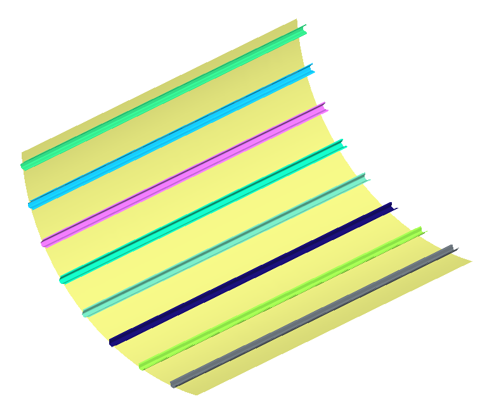
Create Orthotropic Material
- In the main menu, click Settings > Material database.
- Ensure View materials from is set to Material database.
- Right-click on Generic Materials and select Add material in the context menu.
-
Enter the material name and values as shown in the below figure.
Figure 3. 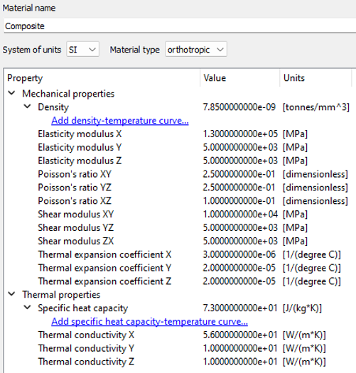
- Click Apply.
- Click Save.
Create Laminates for Stringers
-
In the Assembly workbench, click
 Create
Laminate.
Create
Laminate.
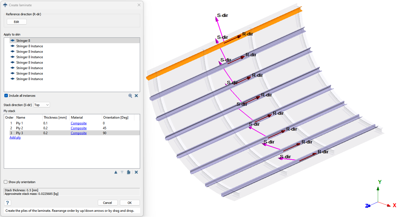
- To add a skin in the Create laminate dialog, select one of the stringer parts from the Project Tree or modeling window.
-
For Stack direction, select Top
from the dropdown.
- Top
- Stacks the plies along the direction of the reference plane as shown in graphics.
- Bottom
- Same as Top but on the other direction of its reference plane.
-
Click Edit under Reference direction
(R-dir).
- To add a ply, click Add ply in the ply stack section. Add 3 plies.
-
Change the thickness of Ply 1, 2, and 3 to 0.1mm,
0.2mm, and 0.2mm
respectively.
Note: Each field in the ply stack section can be made editable by double-clicking on the respective field.
-
Click Select Material to apply material for all the
three plies.
- In the Apply material to Laminate plies dialog, select the Material database radio button.
- Select Composite from the list and click Apply material.
- Set the Orientation for Ply 1, 2, and 3 as 0, 45, 90 degrees respectively.
- Review total Stack thickness and Approximate stack mass shown at the bottom of the dialog.
- Click OK.
Create Laminates for Fuselage Skin
-
In the Assembly workbench, click Create
Laminate.
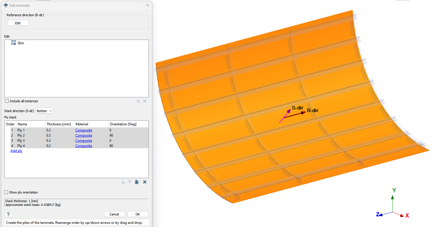
- To add a skin in the Create laminate dialog, select the part named Skin from the Project Tree or modeling window.
-
Click Edit under Reference direction
(R-dir).
-
For Stack direction, select
Bottom from the dropdown.
- Top
- Stacks the plies along the direction of the reference plane as shown in graphics.
- Bottom
- Same as Top but on the other direction of its reference plane.
- To add a ply, click Add ply in the ply stack section. Add 4 plies
-
Change the thickness of Ply 1, 2, 3, and 4 to 0.2mm,
0.3mm, 0.3mm, and
0.2mm respectively.
Note: Each field in the ply stack section can be made editable by double-clicking on the respective field.
-
Click Select Material to apply material for all the
three plies.
- In the Apply material to Laminate plies dialog, select the Material database radio button.
- Select Composite from the list and click Apply material.
- Set the Orientation for Ply 1, 2, 3, and 4 as 0, 90, 0, and 90 degrees respectively.
- Optional:
Select Show ply orientation to view the applied
orientation to the laminate.
Figure 5. 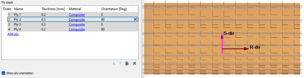
- Review total Stack thickness and Approximate stack mass shown at the bottom of the dialog.
- Click OK.
Review Laminates and Connections
- In the Project Tree, expand the assembly. The skins are now identified as a laminates. Expand the laminate folder to view the plies and their properties.
-
In the Project Tree, expand Connections >
Precise connections.
Note: Precise connections are automatically created between the plies of the laminate.
Apply Material to Remaining Parts
-
Right-click on the assembly in the Project Tree, and
then select Show ➔ Parts without
material.
The parts without material are isolated in the modeling window.
- Select the parts by click and drag selection in the modeling window.
-
In the Assembly workbench, click
 Apply materials.
- Ensure the radio button for Current project is selected.
- Select Aluminum and click Apply to selected parts.
- Click Close.
- Press A to show all parts in the modeling window.
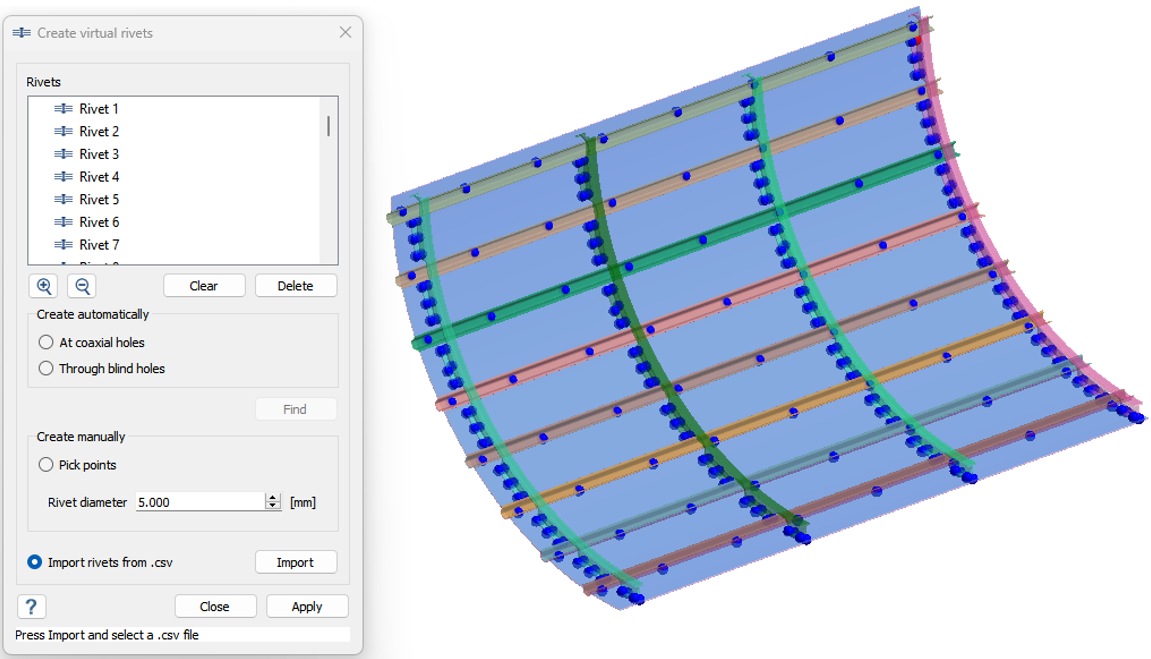
Create Rivets
- In the Connections workbench, click Virtual connectors > Rivets.
- In the Rivets dialog, select the Import rivets from .csv radio button.
- Click Import.
- Select the Rivets.csv file from File Explorer.
- Click OK.
Create Structural Analysis
-
In the main window toolbar, click
 Structural
Analysis > Structural
Linear.
Structural
Analysis > Structural
Linear.
-
In the Analysis Workbench, click
 Immovable
Support .
Immovable
Support .
- In the dialog, verify the Faces radio button is selected.
-
In the modeling window, select faces from all four
sides of the skin.
Figure 8. 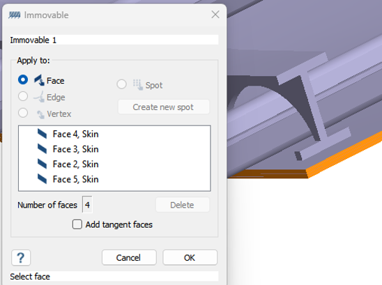
- Click OK.
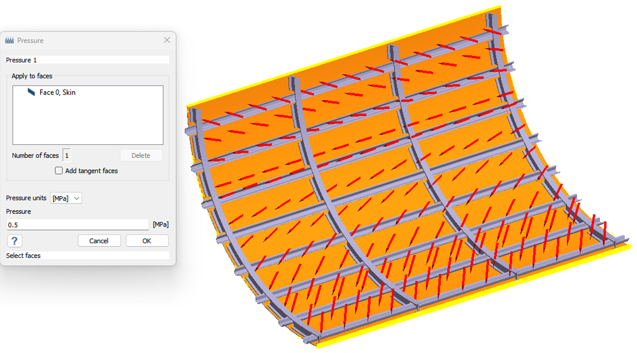
-
In the Analysis Workbench, click
 Pressure >
Uniform Pressure.
Pressure >
Uniform Pressure.
- Select the inner side face of the skin part and enter 0.5 MPa .
- Click OK.
Edit Solution Settings
- In the Analysis branch of the Project Tree, double-click on Solution settings.
- In the Solution settings dialog, for Adaptation select Global+Local in the drop-down menu.
- Click OK.
Run Analysis
- In the Project Tree, open the Analysis Workbench.
-
Click
 Solve.
Review Results
- In the , select Structural 1 subcase.
-
In the Analysis Workbench, click
 Result
plot > Displacement > Displacement magnitude.
The Legend window opens and displays the contour plot.
Result
plot > Displacement > Displacement magnitude.
The Legend window opens and displays the contour plot.