Composite Nets
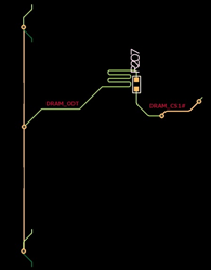 Figure 1. |
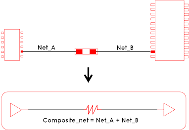 Figure 2. Composite Net Concept |
In the upper left figure, two nets are connected with the R207 resistor, without composite nets operation, these two nets might have open terminal for each then electrical simulation results for the nets wouldn’t be appropriate.
menu provides versatile ways to manipulate the Composite Nets generation and manage features with many options and operations.
In Composite Component Area, you can select components to be used to generate composite net. Two nets connected with this component are modeled as composite nets.
After selecting composite component, upon clicking Generate Composite Nets, the list of composite nets will be displayed on composite net result display region.
You can remove or edit composite net result by clicking Remove or Edit. Also, you can manually add the composite net by clicking Add to select the connected Nets with composite component.
By double-clicking one of composite net, the Edit dialog opens. You can change Net Type, Net Class, and Electrical Constraints.