Assign Simulation Model
- From the menu bar, click : Assign the need simulation model separately for each part.
- From the menu bar, click : Assign RLC model for passive components for each Reference designator.
The Parts dialog shows the status of the properties assignment to the parts which are included in the current PCB system to analyze. The unified parts created by PollEx UPE can have versatile information such as electrical buffer model, package thermal parameters and 3D package geometry which needed for electrical, thermal and 2D/3D assembly analysis (by PollEx DFA and PCB assembly viewer) and it would be stored in specific folders in local or server system.
- Assign the part properties individually when unified parts are not available.
- Assign the part(s) properties automatically when unified parts are available.
From the menu bar, click . The Parts dialog opens. The RLC values of passive component will be displayed automatically if they are defined in CAD file.
In the Link field, you can assign the path of Part library directory and MPN Reference file.
Therefore, there is no check marks which are shown in the Electrical, Thermal, and Reference columns when these are properly assigned. All parts information is assigned (linked) by two methods above will be stored at Parts folder which exists under project directory.
Assign Part(s) Properties Automatically
- From the menu bar, click . The Parts dialog opens.
- In the Part library directory menu, click
 to explore the library path for the unified parts, select the desired
UPFs folder, and click OK.
to explore the library path for the unified parts, select the desired
UPFs folder, and click OK. - Click Synchronize to begin assigning the part properties.
There were no iconic marks which are shown in the Electrical, Thermal, and Reference columns.
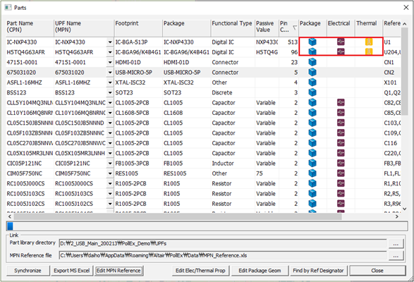
Figure 1. Iconic Marks in Parts dialog
- Contents name under UPF Name column denotes that UPV file exists under local Parts folder for those parts.
- Icon under Package column denotes that 3D package geometry is linked with unified part.
- Icon under Electrical column denotes that electrical buffer model is called from unified part.
- Icon under Thermal column denotes that thermal information is called from unified parts.
Assign Part Properties Individually
When the unified parts are not available, you need to specify the needed part properties separately for each part depending on the desired analysis type. To do analysis, electrical and thermal properties are essential.
To open the Electrical & Thermal Properties dialog, double-click the highlighted H5TQ4G63AFR part.
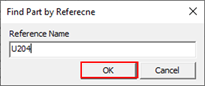
Figure 2.
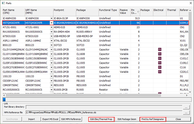
Figure 3. Find Component by Refdesignator Number
- Device Model File: Specify/register the IC models in the form of IBIS,
SPICE, Linear Device, S-Parameter, Package Parasitic, and Y/Z
parameters.
To register and use the model in Linear Device form, this model should be prepared using Linear Device Modeler menu. The model in the form of Package Parasitic should be prepared using Package Pin Parasitic Modeler menu ahead.
- Passive Component Data: Specify the passive components value in the form of RLC, SPICE and S-Parameter.
- Power Rails: Specify the property of power rail for Power Integrity Simulation.
- Package Thermal: Specify the package thermal property for Thermal Analysis.
- Package Pin Parasitic Modeler: Enable to define package pin’s RLC parasitic model having versatile sections and branches.
- Linear Device Modeler: Enable to define simple linear device model for IC pin which will be worked as one of the types among Input, Output, IO or Terminator. Depending on the selected working type of these, you should define the bias and RLC values configuring the circuit topology.
To define a new linear device model or manage it, click Linear Device Modeler in the Electrical & Thermal Properties dialog.
Click Add to define certain model name and it will be shown at SSTL, to define or modify the model SSTL which should be selected by mouse clicking. You can select the model type and assign proper properties requested through two tab menu, for example Model Spec and Model Data.
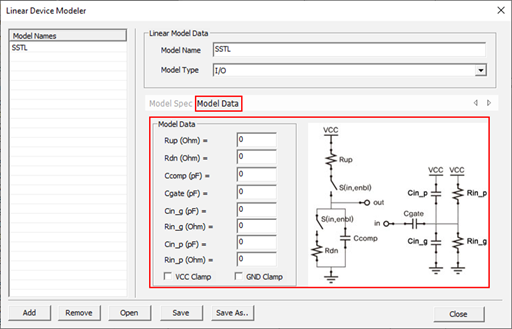
Figure 4. I/O Buffer Model Simulation Parameter
Normally, PollEx SI assigns the same RLC value for the passive component has a same part name. In this menu, you can assign different RLC value for the passive component has different reference designator number.
Upon double-clicking the passive component, the Set Passive Data dialog opens.
In the Set Passive Data dialog, select the Passive Type and enter the Resistance.