This DFE rule checks for the component ground shielding status.
To solve EMI problems, the designer uses shielding signal traces or ground vias. To
solve component EMI problems, the designer can shield a component with mechanical
structures. This method stabilizes the component and protects other signal
effects.
Item: Enter item name.
Check Type: Select required test.
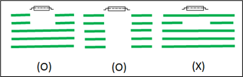
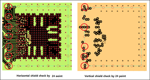
Component Shield: Check if component is fully surrounded with ground
plane, horizontally or vertically.
Fill-Cut: Check if fill-cut exists under the IC.Figure 1.
Inductance Fill Cut: Check if fill-cut exists under the IC. If some
signals exist under the IC, the ground plane should exist between
signal layer and IC placement layer.Figure 2.
Copper Fill: Check if copper-fill exists under the IC. (Top/Bot
Layer)Figure 3.
Pin fill Cut: Check whether the component layer and its lower layer
have been fill cut. The layer below fail if a signal exists before
reaching GND.Figure 4.
Comp: Select a component group that needs shielding.
GND Net: Select a ground net group.
Measure Base: Define a distance measuring object type – COC (Component
Overlap Checking Area), Pad or Silk + Pad.
Distance: Assign a distance from a ground to the measuring object defined in
⑤.
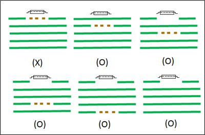
Check Point Count: If you want to check the shield by checking many points
around the component, define the number of checking points in the component.
(4/8/12/16/20/24) If one of the check points does not overlap with ground,
it reports as failed.Figure 5.
Vertical Check: Check vertical shielding. (Ex: Top component: check TOP and
Layer1)
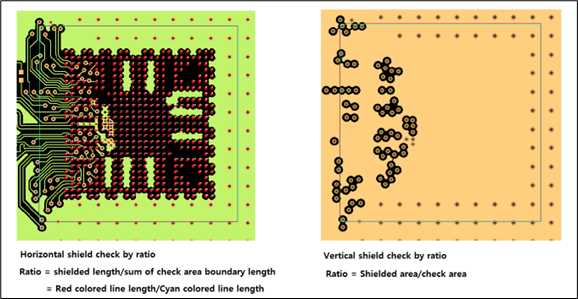
Min Ratio: Define the required minimum shield ratio. If you enable this
option, the check point count value⑦ will be ignored.
Horizontal shield ratio = shield length/sum of check area boundary
length
Vertical shield ratio = shield area/check areaFigure 6.
Min Thermal Via Count: Check the minimum thermal via count under the
component. This option is valid only when you select Component Fill as a
check type option.
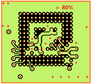
A component that is very sensitive against EMI may affect noise to other patterns or
components. To prevent this, it is better to use ground shielding for the component.
Perfect shielding is impossible. It is reasonably good if the shielding is over 80
percent.Figure 7.