This rule checks for the validity of circuit usage and whether the routing length and
clearance from driver pins are within the specified distance.
When a trace has noise or EMI problems or it is very weak against ESD, the designer
may not have any other routing option to resolve the problem. In such cases, special
purpose circuits may be used. If those circuits are used in design, this DFE rule
checks whether they are used properly. In many cases, those circuits should be
placed near active drivers with controlled signal lengths. For example, damping
resistor circuits should be placed closest to the driver pins.
Item: Enter the item name.
Start Comp: Select a component group that needs a rectification filter
circuit.
Filter Circuit: Select a rectification filter circuit.
Excepted Net: Specify the net that can be excluded from checking (GND,
PWR...)
Distance: Assign distance value to which a rectification filter component
must be located from the staring component.
Net Name Filter: Enter a filter to choose net from nets which are connected
to the selected component.
This rule check reports the following messages:
No Filter: When there is no rectification component in target nets.
No Start Comp: When there is no starting component in target nets.
Distance Fail: When there is a rectification component in target net, but it
violates the distance rule. In this case, it also reports the reference
distance and the measured distance.
Rectification circuit (or filter circuit) is a circuit to pass necessary frequencies
but blocks or eliminates unnecessary frequencies. The purpose of using this filter
is to get stability of the signal. So, for important signals, it is necessary to
check whether those nets have proper types of filters. In fact, it is very difficult
to improper usage of filters without an aid of tools like PollEx DFE.
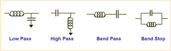
There are four major types of rectification filters: low pass, high pass, band pass
and band elimination (band stop) filters.Figure 1.
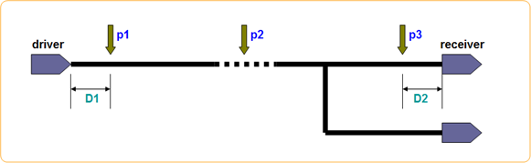
In general, Low Pass filter is used to pass low frequencies and reduce high
frequencies as noise filter. When filters are used, the designer should be cautious
about their locations in signal trace.Figure 2.