Component Position
The Component Position DFE rule checks whether a design follows a component placement guideline.
While component is placed, it is necessary to EMI and ESD problems. For example, high
speed signal generating components are placed at the center of board and they will
affect other parts of the board. In other cases, if components that are weak against
ESD problem are located near the board contour line and shocked by other outside
sources, it causes more serious problems. Because of those reasons, component
keep-out region is needed early in the design stage.
- Item: Enter item name.
- Comp: Select a target component group.
- In/Out: Select a check area type - inner or outer side from the reference
area set in item ④.
- In: If the component is inside the defined area, it reports as passed.
- Out: If the component is inside the defined area, it reports as failed.
- Area: Select a reference location check region.
- Center/Left/Right/Top/Bottom/LeftTop/LeftBottom/RightTop/RightBottom/Edge
- Area Size (%): Assign a ratio criteria as a percentage of PCB length.
Result
- Check whether there is a target component in the inner or outer region.
- For the user-defined region, change its display into polygon with blue
outlines. The component is highlighted green.
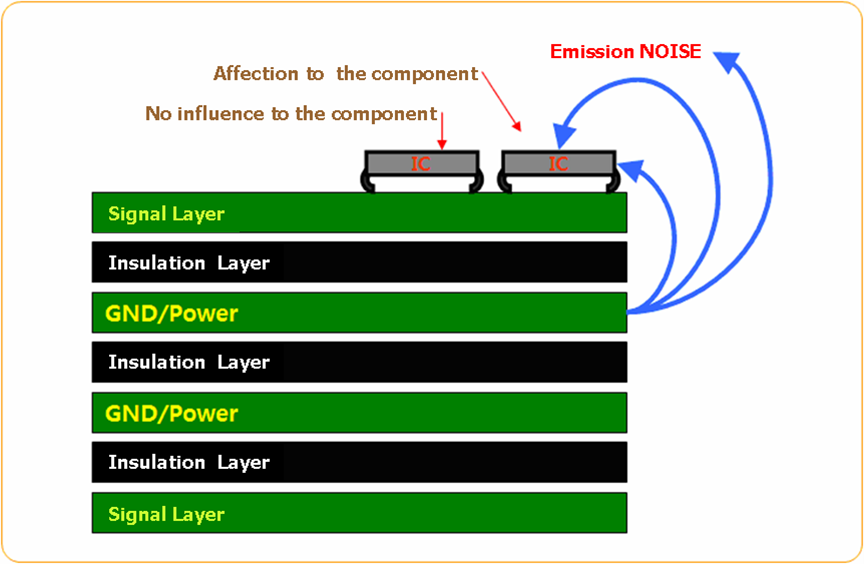
Figure 1.