Hole and Bridge
- Hole Variant Layer: Sets the hole layer.
- Hole Variant Area
Figure 2. 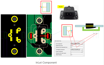
- Inlet Component: As shown in Figure 2, set the corresponding component.
- Expand InLet Area: Specify the size of the InLet Component's fixed pin to be expanded.
- Clearance from Expanded InlLet: Specify the separation distance that covers the bottom surface of the input component.
- Overlapping Component: When creating Soldering Pallet area, Pallet Area is created using Hole Variant Data. Pallet Area cannot invade the COC Area of the part. However, the part set as the overlapping component allows the invasion of the COC area.
- Clearance from Hole Variant: Distance between Hole Variant Barrier from hole Variant area.
- Pallet Thickness: Thickness of Hole Variant Barrier.
- Bridge: Bridge refers to the section connecting each Hole Variant area. The
creation of the bridge is created over a certain width, avoiding the part
area. When the separation distance between parts cannot be secured when
creating a bridge, the bridge can be created across a specifically allowed
component. Soldering Pallet area created in each Hole Variant area must have
more than a certain number of connected bridges.
Figure 3. 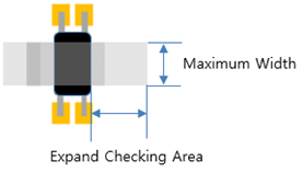
Figure 4. 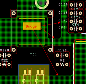
- Maximum Width: Set the maximum width of the bridge that occurs on the Allowed Component.
- Expand Checking Area: The area where the maximum width of the bridge should be maintained.
- Allowed Component to Hole Variant Area: Set the separation distance between Allowed Component and Hole Variant Area.
- General Minimum Width: The minimum width of the created bridge. It should be created wider than the set value.