General
The General tab of the Generate-Input dialog opens.
- Soldering Direction: Sets soldering direction.
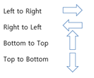
Figure 1. - Output Data: Generated Pallet area are saved as individual layers. Sets each
layer name. Default layer names will be given initially.
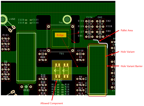
Figure 2. - Option
- Edit Component DB: Create a new Component DB or read or modify the
Component DB file used in Text format (*.txt). When you click
Edit DB, the Component Group
Manager dialog opens.
- Section for list-up Component Group.
- Add: Can add new Component Group or select the saved Component Group. Can select component groups used in text format (*.txt). To the selected component group, you can add parts using the Naming, Filter, and Comment functions.
- Delete: Can delete Component Group.
- Naming: Classifies by name of Part, Reference, Footprint, and Package when generates Component Group.
- Filter: Classifies by naming string of Part, Reference, Footprint, and Package when generates Component Group.
- Comment: Classifies by comment of properties in Part, Reference, Footprint, and Package when generates Component Group.
- Save: Saves setting contents as file(design_name.pccls).
- Save as: Saves as file (*.pccls).
- Load: Loads the file (*.pccls).
- Rounding Corner Arc Diameter: Sets the radius value of arc when curving the corners of the generated data.
- Generation Level: Gives the grid size to make bridge among soldering pallet area.
- Level 1 = 1, Level 2 = 0.5, Level 3 = 0.25
- Edit Component DB: Create a new Component DB or read or modify the
Component DB file used in Text format (*.txt). When you click
Edit DB, the Component Group
Manager dialog opens.