Defining VTS Data, Billet Taper, HTC, Symmetry BC,
and Porthole
Use the Process Data tool to define the variable time step (VTS) data, billet taper, and heat transfer
coefficient.
Defining the Variable Time Step Automatically
Transient analysis requires specification of time step data. Metal extrusion is a
cyclic process and duration of each cycle is depends on:
Ram speed
Ram acceleration time
Upset billet length
Butt length
Inspire Extrude automatically decides the time step data to be used
based on the above values. Hence, automatic time step determination is the preferred
approach. However, the time step data can be edited and modified using the Process Data tool.
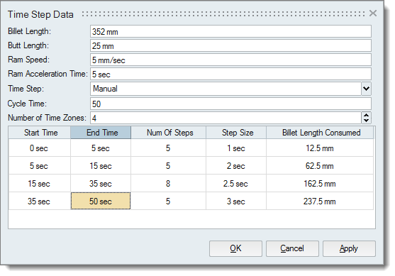
From the Extrusion ribbon, Process Data tools, click VTS.
The Time Step Data dialog is displayed.
In the Billet Length field, set the length of the upset
billet. This value should match the length of the billet created. You can
measure and verify this.
In the Butt Length field, set the length of the butt. This
value is typically 1-inch. For shorter billets, if actual value is not known,
use 1-inch or 10% of the billet – whichever is smaller. For example if the
billet length is only 5 inches, specify 0.5 in as the butt length.
In the Ram Speed field, enter the speed at which the punch
(also referred to as dummy block or ram stem) moves.
Select either Auto or Manual for
the Time Step. Auto is preferred.
Defining the Variable Time Step Manually
The Manual option in the Time Step Data dialog is used to
control and change the time step for a transient problem. This allows you to define
up to five different time step sizes during the cycle (referred to as zones).
Inspire Extrude automatically estimates the cycle time. You can reduce
this cycle time to solve for less than full cycle analysis.
From the Extrusion ribbon, Process Data tools, click VTS.
The Time Step Data dialog is displayed.
In the Billet Length field, set the length of the upset
billet. This value should match the length of the billet created. You can
measure and verify this.
In the Butt Length field, set the length of the butt. This
value is typically 1-inch. For shorter billets, if actual value is not known,
use 1-inch or 10% of the billet – whichever is smaller. For example if the
billet length is only 5 inches, specify 0.5 in as the butt length.
In the Ram Speed field, enter the speed at which the punch
(also referred to as dummy block or ram stem) moves.
Select Manual for the Time Step.
To reduce the number of cycle times, enter a new value.
Select the number of time zones.
For each time zone, you can change only the End
Time and Num Of Steps. The rest
of the data is automatically computed.
Click OK.
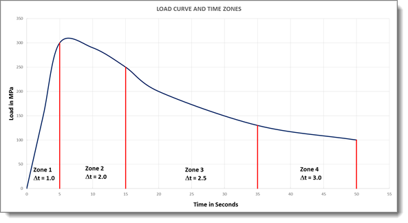
The following image shows how the time step size in four zones in the table
above correspond with the load curve. When the solver is computing the
solution, between 0 – 5.0 s, it uses a time step size of 1 second. That is,
you will be able to inspect the solution in the post-processor after every
second. Then between 5.0 and 15.0 second, it will advance the time in 2 s
steps. That is, it will move from 5.0, 7.0, 9.0, 11.0., 13.0, and 15.0. In
the same way for the remaining two time zones it will 2.5 and 3.0 s as time
step sizes. Inspire Extrude allows you to have from 1 to 5 time
zones in defining the time step. It should be noted that the quality of the
solution computed is not affected by the size of the step.
Setting Up the Billet Taper
Create the billet before setting up the billet taper.
During extrusion there is heating due to stress work which causes the temperature of
the profile to increase during the cycle. This may lead to poor and inconsistent
product quality. In order to overcome this, tapered billet heating is used. Inspire Extrude supports the combination of all three types of tapered
heating:
Axial taper
Lateral taper
Radial taper
Inspire Extrude enables you to specify this data as used in the
extrusion process. This data is relevant and useful only for transient analysis. If
you are performing a steady state analysis or bearing optimization analysis, there
is no need to specify this data.
From the Extrusion ribbon, Process Data tools, click Billet
Taper.
The Billet Taper Data dialog is displayed.
In the Cycle No column, specify the number cycles to
perform the analysis. Inspire Extrude limits the number of cycles to
a maximum of 5.
However, the solver places no limit on this value for simulation. Solvers
have a limit that is based on different starter billets and tapers that can
vary from cycle to cycle. Taper data used for cycles 1 to 5 can be different
from each other; after that, the solver will use the 5th cycle data for rest
of the cycles. Computational time for each cycle will be approximately five
times the CPU time of steady state analysis, which should be kept in mind
when doing a large multi-cycle analysis. In this release, if you would like
to do more than 5 cycles, you will have to manually modify the
*.hx file and increase this parameter.
Complete the rest of the fields as required.
Click OK.
Billet Taper Examples
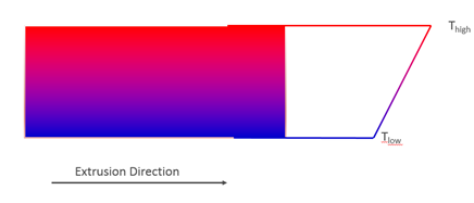
Axial Taper
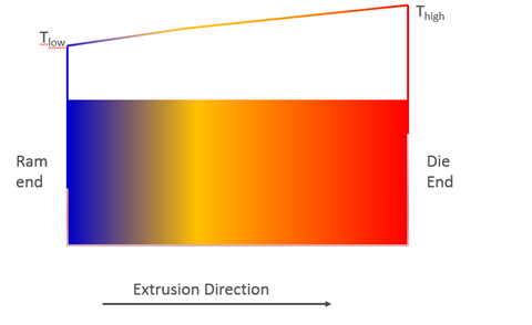
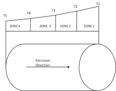
When axial taper is used, temperature of the billet varies along axial
direction. This variation can be specified as five zones, each with a linear variation.
Billet is hotter on the die end and it is at billet preheat temperature and it is colder
(relatively) on the ram end. Images below show the variation and how zones are counted in
the solver.
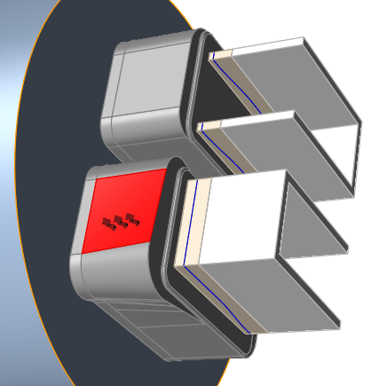
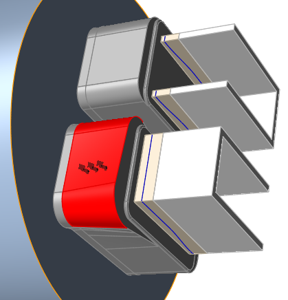
Lateral Taper
When billet is loaded in the container, the bottom portion of the billet comes in contact
with the container. Hence, there will be differences in heat transfer rates at the bottom
and top portion of the billet and it results in lateral variation of temperature. This
gradient becomes important when extruding multiple profiles from a single billet. To
compensate for the difference in heat transfer rates, billet may be heated non-uniformly in
lateral direction. Later taper data is used to specify this gradient. The image below shows
how temperature varies from bottom to top of the billet. In data specification, it is
possible make either side (top or bottom) hotter than the other side.
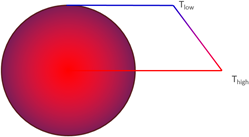
Radial Taper
During extrusion, billet peripheral regions undergo excessive deformation compared to the
core region and hence at a higher temperature. To compensate for this, non-uniform radial
heating of the billet is used.
Defining Heat Transfer Coefficient
Select faces to specify heat transfer boundary
conditions.
From the Extrusion ribbon, Process Data tools, click the HTC
tool.
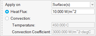
Select a surface to apply the HTC boundary condition.
Press Ctrl and click surfaces on the model to add or
remove boundary conditions by toggling between selected and unselected. Hold Ctrl to add multiple faces to the same
boundary condition.
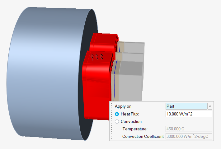
Enter the values in the microdialog to assign its heat
transfer properties.
Note: Apply the HTC on either selected surfaces or the
entire part. If you select Part, the HTC will be
applied on all of the surfaces of the part.
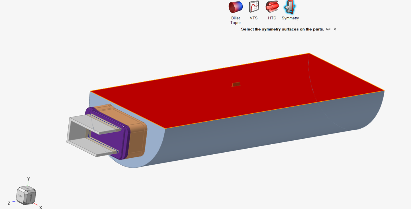
Defining Symmetry Boundary Conditions
Symmetry is used for specifying the symmetry planes.
If your model has symmetry, take the following
steps.
From the Extrusion ribbon, click the Process
Data icon.
Click Symmetry.
Select the Symmetry surfaces
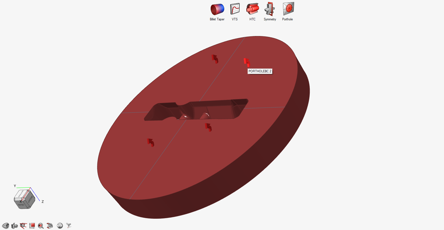
Defining Porthole Boundary Conditions
Set the boundary conditions for split surface regions of a single
porthole.
This feature lets you track material entering via
different regions of a single porthole. To create different regions, use the tools in
the Geometry ribbon to split and organize the inlet surface. Material entering via each
one of the regions is tracked by the weld-strength module. This feature is needed for
bridge dies and other similar ones that might have only a single porthole that cannot be
split otherwise.
Note: This advanced feature is not supported for
models containing multiple portholes.
From the Extrusion ribbon, click the Process
Data icon.