
Advanced Bearing Features
Setting up Bearing Reference Surfaces
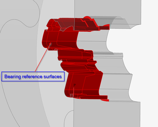
Use the BRS tool to select bearing reference surfaces.
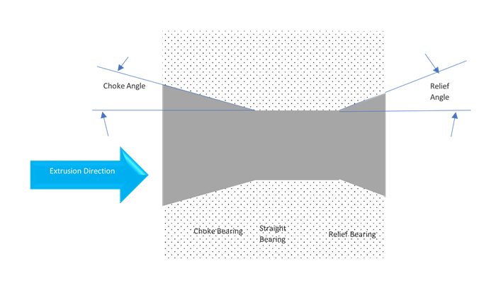
For such models, the automatic meshing of the bearing region that includes a choke region with a solid mapped mesh of triangular prism elements, might not always succeed. To avoid this potential failure, the solver allows the possibility of modeling the choke and relief regions using the bearing reference surfaces extracted from the tool geometry.
Solution methodology:
-
Extract the bearing reference surfaces from the die geometry.
-
Mesh the bearing solid with no choke/relief.
-
Use the 2D mesh of the reference surfaces to determine the choke angle and estimate the friction.
Creating Bearing Reference Surfaces
Use the BRS tool to select bearing reference surfaces.
- Click the Extrusion ribbon.
-
Click the Advanced Bearing icon.
-
From the secondary toolbar, click on the Bearing Reference
Surface tool.
Inspire Extrude will automatically detect all of the bearing reference surfaces on the tool geometry.Automatically detected surfaces are shown in red.
-
Press Ctrl and click surfaces on the model to add or
remove surfaces by toggling between selected and unselected.
Press Ctrl and drag to draw a box and deselect a group of surfaces even if they are hidden behind other layers.
To deselect a single surface behind another surface, select that front surface and press H to hide it first.
Note: Pressing H toggles the last selected surface between hidden and shown. Pressing S will show all of the hidden surfaces. - Right-click and mouse through the check mark to exit, or double-right-click.
Setting up Variable Bearing Start
Use this tool to extract the Bearing Start curve, which varies in the Z direction and is part of the Pocket geometry.
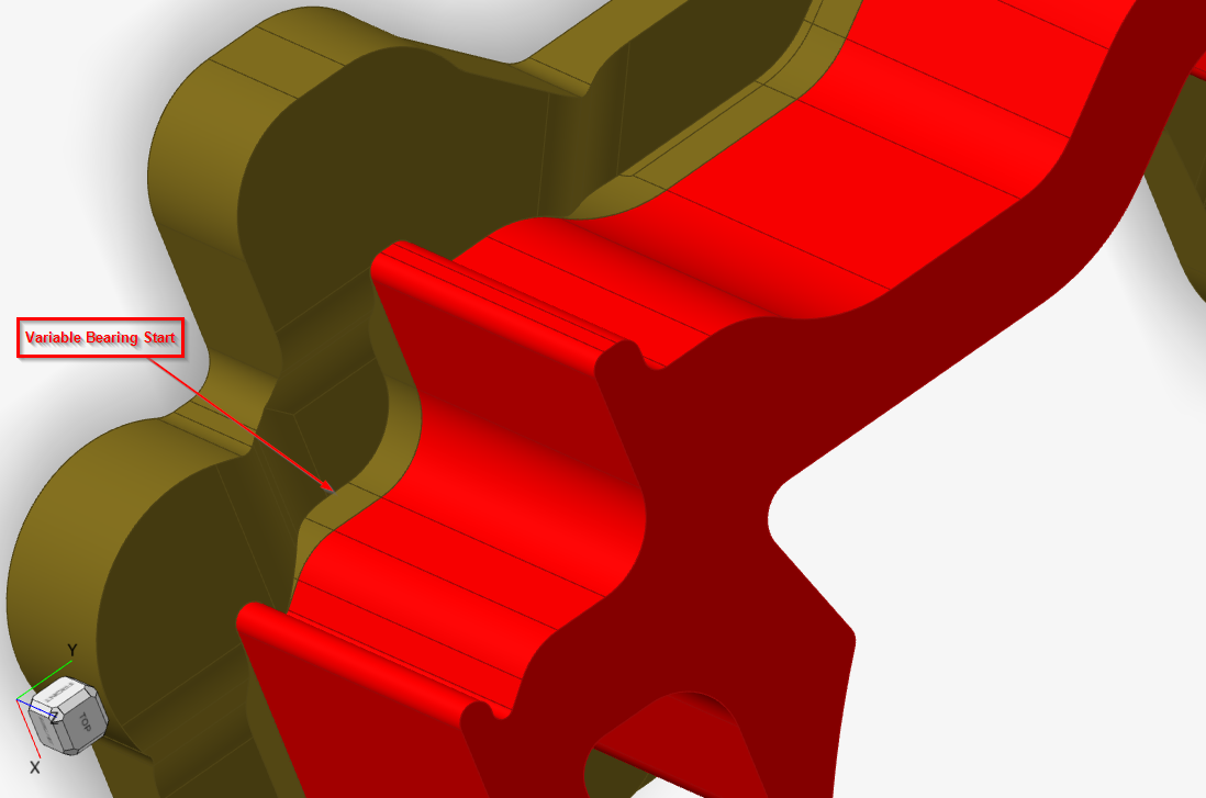
For ease of capturing this curve, display only the relevant pocket component when you enter the Bearing Start Curve context. It will show this solid in an edge mode.
- Click the Extrusion ribbon.
-
Click the Advanced Bearing icon.
-
From the secondary toolbar, click on the Bearing Start
Curve icon.
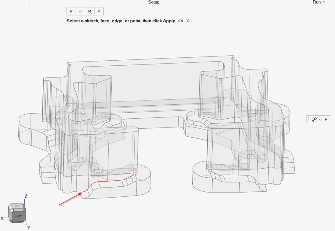
This internally activates the Extract edge context. After this, display the bearing solid. This will make it easier to visualize and capture the curve.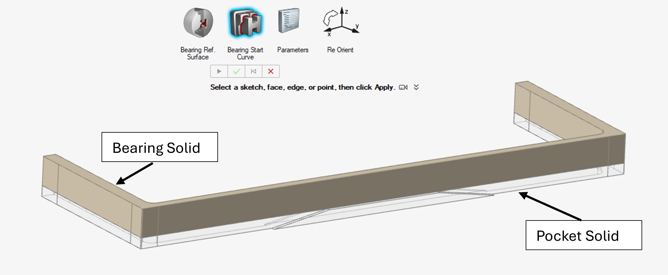
-
Select the edges that form the Bearing Start Curve. As you select, the curve
will be shown in red.
-
After you select all the edges, click on the Play icon in the micro dialog and
exit the context.
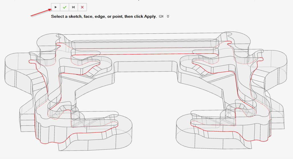
This will create a new part in the model browser with these selected edges. -
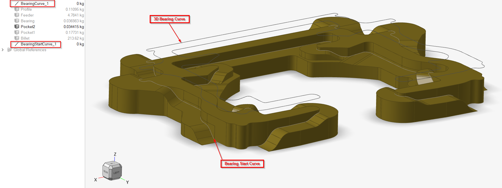
Rename this new part to match its corresponding 3D Bearing curve.
For example: Bearing3D curve is BearingCurve_1, then its corresponding start curve should be named as BearingStartCurve_1. You can either rename it manually or, to do it automatically, right-click on the part, and then click on Organize As and select BearingStartCurve.
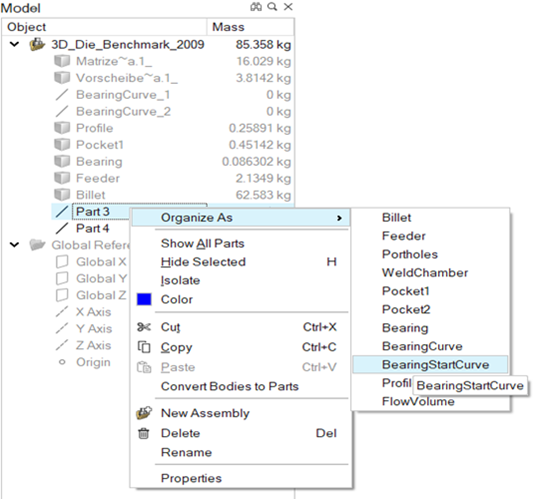
This naming convention has to be followed so that the start curve is detected and processed in the data deck creation.
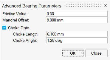
Setting Up Advanced Bearing Parameters
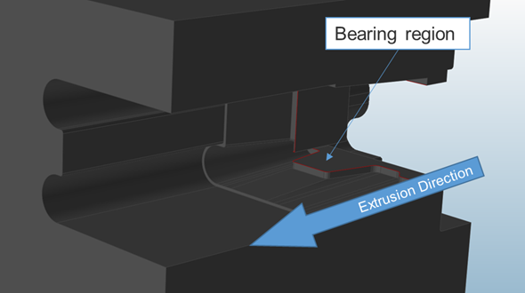
Set up choke, relief, and friction parameters for the bearing curve.
- Click the Extrusion ribbon.
-
Click the Advanced Baring icon.
-
From the secondary tool bar, click on the Parameters
tool.
-
Select the bearing curve to adjust friction, mandrel offset, and choke
data.
Curves should be selected one at a time. Bearing lengths are adjusted automatically.
Reorienting the Model
Align the model to its original position in order to import optimized data back into CAD.
- Click the Extrusion ribbon.
-
Click the Advanced Baring icon.
-
From the secondary toolbar, click the Re Orient tool.
