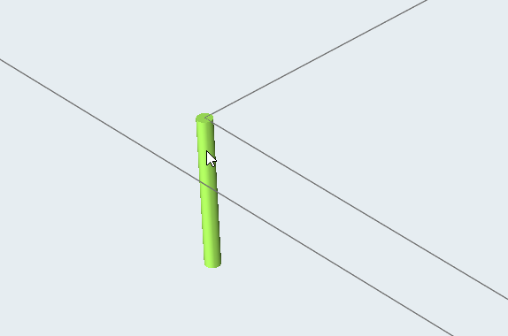
Creating the Bearing Profile
Specify the bearing region using the Bearing tool.
Creating the Bearing
Use the Bearing tool to create the bearing.
-
From the Extrusion ribbon, click the Bearing tool.

-
Select the die opening surface from which bearing region starts.
The bearing and profile parts are created.
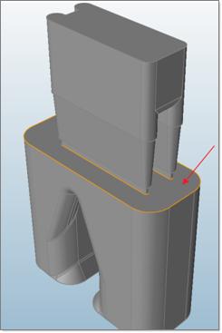
-
Adjust the bearing and profile length in the modeling window.
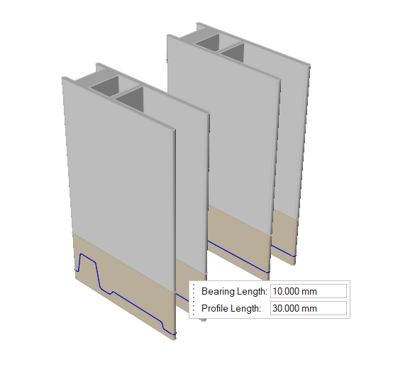
- Right-click or click Esc to apply the changes to the model.
Setting Up the Bearing Optimization
Use the Bearing tool to setup the bearing optimization.
-
From the Extrusion ribbon, click the Bearing tool.

-
Select the bearing curve to setup for optimization.
Curves should be selected one at a time.The first time this action is done, vertical bearing lines for all the curves are created. This is a one-time operation; be sure to let the process finish. Once completed, the selected curve along with its extracted vertical bearing lines are displayed. The goal of this process is to classify these lines into different groups.
Editing Bearing Lines
Bearing lines can be edited only after a bearing curve is created.
-
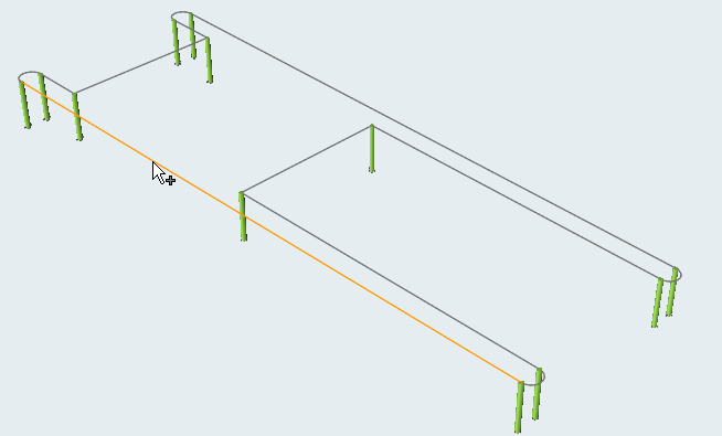
Double click on any extracted bearing curve.
Bearing edit context is activated. All the vertical bearing lines will be extracted and displayed. Vertical bearing lines are created based on the points that form the bearing curve.
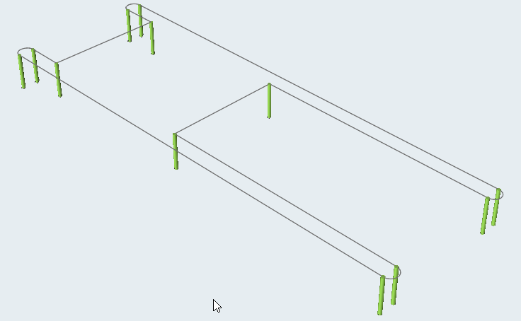
-
To add a vertical bearing line, click on the bearing curve at the required
position.
-
To delete a vertical bearing line, hover your mouse over the vertical bearing
line and press the Delete key.
