Design Space
A design space is the initial geometry that forms the boundary of the optimized shape.
It is typically a simplified representation of the existing part, with holes and pockets removed. Increasing the material available in the design space will yield a more optimized result.
You can create a design space by using the modeling tools in Inspire or by importing parts from other solid modelers, and then designating the relevant parts as a design space using the right-click context menu or the Property Editor.

Design Spaces for Topology Optimization
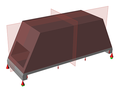
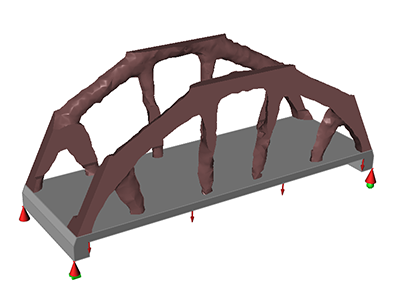
In topology optimization, a design space is the initial part from which material is removed until a final shape is reached during optimization.

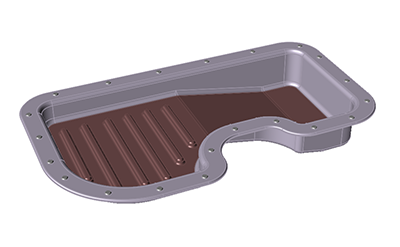
Design Spaces for Topography Optimization

Design and Non-Design Spaces
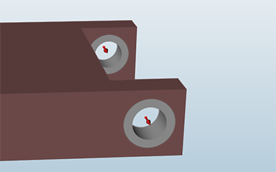
In general, it is best not to apply loads and supports directly to design spaces, as this often leads to incorrect results. Instead, you should split the part into design and non-design spaces and apply loads and supports to the non-design spaces.

Creating a Design Space
A design space can be defined by any solid or surface.
A part that is used as a design space should not be very detailed. To ensure the most freedom to generate a shape, you should use the simplest design space possible. The more fine details you have in the design space, the longer it will take to run the optimization.
-
To designate a part as a design space right-click on a part.
You can select multiple parts by left-clicking while holding down the Ctrl key, and then right-click one of the selected parts.
-
Select Design Space from the context menu.
The selected parts are now designated as design spaces and are displayed as reddish brown in the modeling window.