In this law the material behaves as linear elastic when the equivalent stress is
lower than the yield stress.
For higher value of stress, the material behavior is plastic. This law is valid for
brick, shell, truss and beam elements. The relation between describing stress during
plastic deformation is given in a closed form:(1)
Where,
Flow stress (Elastic + Plastic Components)
Plastic strain (True strain)
Yield stress
Hardening modulus
Hardening exponent
Strain rate coefficient
Strain rate
Reference strain rate
Temperature exponent
Tmelt
Melting temperature in Kelvin degrees. The adiabatic conditions are
assumed for temperature computation:(2)
Where,
Specific heat per unit of volume
Initial temperature (in degrees Kelvin)
Internal energy
Two optional additional inputs are:
Maximum flow stress
Plastic strain at rupture
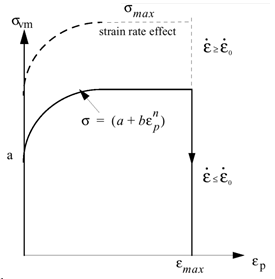
Figure 1 shows a typical
stress-strain curve in the plastic region. When the maximum stress is reached during
computation, the stress remains constant and material undergoes deformation until
the maximum plastic strain. Element rupture occurs if the plastic strain is larger
than . If the element is a shell, the ruptured element is
deleted. If the element is a solid element, the ruptured element has its deviatoric
stress tensor permanently set to zero, but the element is not deleted. Therefore,
the material rupture is modeled without any damage effect. Figure 1. Stress - Plastic Strain Curve
Regarding to the plastification method used, the strain rate expression is different.
If the progressive plastification method is used (that is, integration points
through the thickness for thin-walled structured), the strain rate
is:(3)(4)
With global plastification method:(5)
Where, is the internal energy.
For solid elements, the maximum value of the strain rate components is
used:(6)
Strain Rate Filtering
The strain rates exhibit very high frequency vibrations which are not physical. The
strain rate filtering option will enable to damp those oscillations and; therefore obtain
more physical strain rate values.
If there is no strain rate filtering, the equivalent strain rate is the maximum value
of the strain rate components:(7)
For thin-walled structures, the equivalent strain is computed by the following
approach. If ε is the main component of strain tensor, the kinematic assumptions of
thin-walled structures allows to decompose the in-plane strain into membrane and
flexural deformations:(8)
Then, the expression of internal energy can by written as:(9)
Therefore:(10)
The expression can be simplified to:(11)(12)
The expression of the strain rate is derived from Equation 8:(13)
Admitting the assumption that the strain rate is proportional to the strain, that
is:(14)(15)
Therefore:(16)
Referring to Equation 12, it can be seen that
an equivalent strain rate can be defined using a similar expression to the
equivalent strain:(17)(18)
For solid elements, the strain rate is computed using the maximum element
stretch:(19)
The strain rate at integration point, in /ANIM/TENS/EPSDOT/i is calculated by:(20)
Where,
Membrane strain rate /ANIM/TENS/EPSDOT/MEMB
Bending strain rate /ANIM/TENS/EPSDOT/BEND.
The strain rate in upper and lower layers is computed by:(21)
/ANIM/TENS/EPSDOT/UPPER(22)
/ANIM/TENS/EPSDOT/LOWER
The strain rate is filtered by using:(23)
Where,
Time interval
Fcut
Cutting frequency
Filtered strain rate
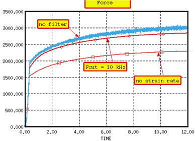
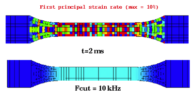
Strain Rate Filtering Example
An example of material characterization for a simple tensile test RD-E: 1100 Tensile Test is given in Radioss
Example Guide. For the same example, a strain rate filtering allows to remove high
frequency vibrations and obtain smoothed the results. This is shown in Figure 2 and Figure 3 where the cut frequency Fcut = 10 KHz is used. Figure 2. Force Comparison Figure 3. First Principal Strain Rate Comparison (max = 10%)