As for the four node shell element, a simple linear Mindlin Plate element formulation is
used. Likewise, the use of one integration point and rigid body motion given by the time
evolution of the local reference frame is applied. There is no hourglass mode in case of one
integration point.
Local Reference Frame
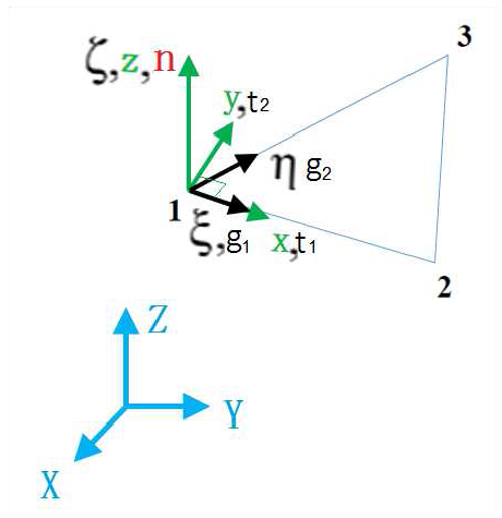
The local reference frame for the three node shell element is shown in Figure 1.Figure 1. Node Shell Local Reference Frame
The vector normal to the plane of the element is defined as:
The vector defining the local x direction is defined as edge 1-2:
Hence, the vector defining the local y direction is found from the cross product of the two
previous vectors:
Time Step
The characteristic length for computing the critical time step is defined
by:
Three Node Shell Shape Functions
The three node shell has a linear shape functions defined as:
These shape functions are used to determine the velocity field in the
element:
Membrane Behavior
The method used to calculate the membrane behavior and the membrane strain rates is exactly
the same as that used for four node shell elements (Membrane Behavior).
Bending Behavior
The bending behavior and calculation of the bending strain rates (or curvature rates) is
the exact same method used for four node shell elements (Bending Behavior).
Strain Rate Calculation
The strain rate calculation for the three node shell is the same as the method used for the
four node shell. However, only three nodes are accounted for. This makes the vectors and
matrices smaller. The overall membrane strain rate is calculated by:
Where the matrix of shape function gradients is defined
as:
Where for a shell element.
The overall bending strain or curvature rate is computed by:
Where,
Mass and Inertia
The three node shell element is considered as an element with a lumped mass. Its mass is
defined as:
Where,
Material density
Shell thickness
Reference plane surface area
The mass moment of inertia about all axes is the same:
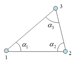
When nodal masses need to be calculated, the distribution is determined by the shape of the
element as shown in Figure 2.Figure 2. Mass Distribution