Abscissa scale factor for
pressure based functions.
Default = 1.0 (Real)
AscaleS
Abscissa scale factor for
area based functions.
Default = 1.0 (Real)
AscaleA
Abscissa scale factor for
angle based functions.
Default = 1.0 (Real)
AscaleD
Abscissa scale factor for
distance based functions.
Default = 1.0 (Real)
mat_ID
Initial gas material
identifier.
(Integer)
Pext
External
pressure.
(Real)
T0
Initial
temperature.
Default = 295K (Real)
Iequil
Initial thermodynamic
equilibrium flag.
= 0
The mass of gas initially filling the airbag is
determined with respect to the volume at time zero.
= 1
Start of the FVM simulation is shifted to TTF (time to
fire) specified in an injector sensor.
(Integer)
Ittf
Time shift flag.
Active
only when at least one injection sensor is specified. Determines
time shift for venting and porosity options when injection
starts at a Time to Fire specified in a sensor.
Polyhedron airbag volume meshing based on geometric
plane cutting.
= 2
Tetrahedron airbag volume meshing using internal and
external airbag surfaces.
= 4
Tetrahedron airbag volume meshing using internal and
external airbag surfaces with output of the created
tetra mesh in Radioss
format.
= 12
Tetrahedron airbag volume meshing using internal and
external airbag surfaces using the HyperMesh tetramesher.
= 14
Tetrahedron airbag volume meshing using internal and
external airbag surfaces using the HyperMesh tetramesher. The
tetra mesh is output in the Radioss format to a file.
(Integer)
Tswitch
Amount of time after
airbag time to fire to switch from FVM to UP (Uniform Pressure)
formulation. 31
Default = 1e30
(Real)
Iswitch
Flag to switch from FVM to UP.
= 0 (Default)
No switch to uniform pressure. The finite volume method
is used.
= 1
Switch to uniform pressure is performed when either
Pswitch
or
Tswitch
criteria is reached.
= 2
Switch to single finite volume is performed when either
Pswitch
or
Tswitch
criteria is reached.
(Integer)
Pswitch
Ratio of FV standard
deviation pressure to average pressure which triggers FVM to UP
switch. 33
Using /DT/FVMBAG in the Engine will
override this value.
Default = 0.9
Minimum time step for the
airbag.
Using /DT/FVMBAG in the Engine will
override this value.
Ilvout
Output level.
= 0 (Default)
Limited information about FVM airbag is printed
out.
= 1
All possible information about FVM is printed out.
(Integer)
Nlayer
Estimated number of layers
in airbag folding along direction . 23
Default = 10
(Integer)
Nfacmax
Estimated maximum number
of airbag segments concerned by a finite volume in the first
automatic meshing step.
Default = 20 (Integer)
Nppmax
Estimated maximum number
of vertices of a polygon.
Default = 20 (Integer)
Ifvani
Write finite volumes in
Radioss Starter Animation A000 File flag.
= 0
No
= 1
Yes
(Real)
Comments
The airbag external surface
should be built only from 4- and 3-noded shell elements. The airbag external surface
cannot be defined with option /SURF/SEG, nor with
/SURF/SURF, if a sub-surface is defined in
/SURF/SEG.
External surfaces shall compose
a closed volume with normals must oriented outwards.
Abscissa scale factors are used
to transform abscissa units in airbag functions, for example:(1)
Where,
Time
Function of
fct_IDt
(2)
Where,
Pressure
Function of
fct_IDP
The options are obsolete. Normally, the curve scaling parameters are
used instead.
Pressure and temperature of
external air and the initial pressure and temperature of air inside of airbag is
set to Pext and T0.
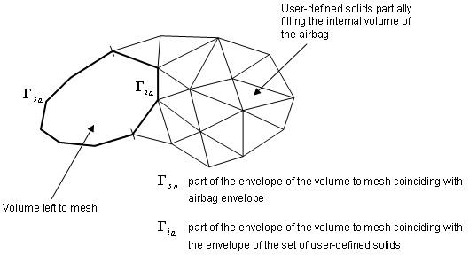
The gas flow in
FVMBAG1 is solved using finite volumes.
Some of these
finite volumes can be entered by you through a group of solids, located inside
the airbag and filling a part or the total internal volume. If there still
exists a part of the internal volume which is not discretized by user-defined
solids, an automatic meshing procedure produces the remaining volumes. This can
be used for example to model a canister.
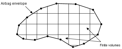
A finite volume consists in a set
of triangular facets. Their vertices do not necessarily coincide with the nodes
of the airbag. The airbag envelope can be modeled with 4-node or 3-node
membranes; however, 3 nodes are recommended. Figure 1. Figure 2.
Venting through vent
holes:
If Iform = 1,
venting velocity is computed from Bernoulli equation using local pressure in
the airbag.
The exit velocity is given by:(3)
The mass out flow rate is given by:
If Iform = 2,
venting velocity is computed from the Chemkin equation:(4)
Where, is defined by
fct_IDv.
If
Iform = 3,
venting velocity is equal to the component of the local fluid velocity
normal to vent hole surface. Local density and energy are used to compute
outgoing mass and energy through the hole.
When there is no sensor which
activates gas injection, the vent holes and porosity becomes active, if time
T becomes greater than the Tstart, or if the pressure
P exceeds
Pdef value longer than the time
given in .
When at least one of the
injectors is activated by the sensor, then activation of venting and porosity
options is controlled by
Ittf.
Tinj
is the time of the first injector to be activated by the
sensor.
Ittf =
0
Venting,
Porosity
Activation
When longer than the time , or
Deactivation
Tstop
Time dependent
functions
No shift
Ittf =
3
Venting,
Porosity
Activation
When and longer than the time , or
Deactivation
Time dependent
functions
Shifted by
All other related curves are active when the corresponding
venting, porosity or communication option is active.
The variety of
Ittf values comes from
historical reasons. Values
Ittf=1 and
2 are obsolete and should not be used. Usual values are
Ittf=0 (no
shift) or
Ittf=3
(all relative options are shifted by
Tinj).
If surf_IDv ≠ 0 (surf_IDv is defined) the vent hole area is
computed as:(5)
Where,
Area of surface surf_IDv
Initial area of surface surf_IDv
, and
Functions of
fct_IDt,
fct_IDP and
fct_IDA
In the case of activated venting closure
the vent holes surface is computed as:(6)
(7)
With impacted surface:(8)
and non-impacted surface:(9)
Figure 3.
Where for each element e of the vent holes surf_IDv, means the number of impacted nodes among the nodes defining the
element.
A0 is the initial area of
surface surf_IDv
ft,
fP and
fA are functions of
fct_IDt,
fct_IDP and
fct_IDA
ft',
fP' and
fA' are functions of
fct_IDt',
fct_IDP' and
fct_IDA'
Radioss ends with a Starter error, if surf_IDv = 0 (surf_IDv is not defined) (Iform=1 or 2).
Functions
fct_IDt and
fct_IDP are equal to
1, if they are not specified (null identifier).
Function
fct_IDA is assumed to be equal
to 1, if it is not specified.
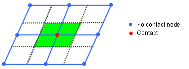
To account for contact
blockage of vent holes and porous surface areas, flag
IBAG must be set to
1 in the correspondent interfaces (Line 3 of interface
/INTER/TYPE7 or /INTER/TYPE23). If not, the
nodes impacted into the interface are not considered as impacted nodes in the
previous formula for Aimpacted
and Anon_impacted.
Leakage by porosity
formulations, the mass flow rate flowing out is computed as:
Iformps =
1 (Isentropic - Wang Nefske)
Iformps = 2
Where, v is the outflow gas velocity
(Chemkin)
Iformps =
3 (Graefe)
The effective venting area
Aeff is computed according
to the input in the /LEAK/MAT input for fabric materials of
TYPE19 or TYPE58.
If leakage blockage is
activated, Iblockage=1, the effective venting
area is modified as:(10)
The blockage will be active
only if flag IBAG is set to
1 in the concerned contact interfaces (line 3 of interface
TYPE7 and TYPE23).
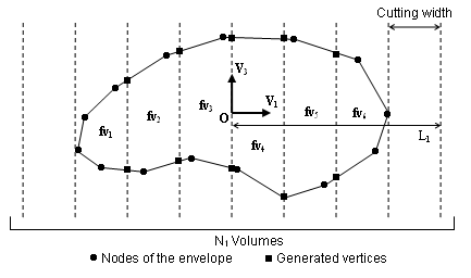
Automatic finite volume
meshing parameters.
The finite volumes are
generated in two steps.
The first step generates vertices lying exclusively on the envelope of the
airbag. You can update the finite volume along with the deformation of
the envelope and correspond to the following procedure (displayed in 2D
for purpose of clarity): Figure 4.
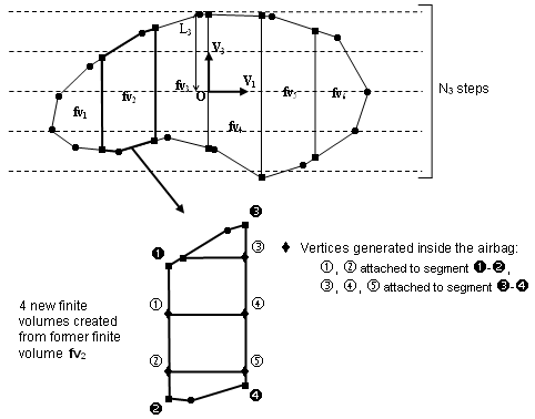
This procedure requires the input of the direction , named cutting direction, and of the
direction . A second direction in the plan normal to the cutting
direction will be computed. In order to position the finite volumes
and to determine the cutting width in both direction and , an origin O must
be provided as well as a length
Li, counted
both positively and negatively from the origin, and a number of
steps Ni. The
cutting width is then given by:(11)
It is required that the box drawn in the
horizontal plane (normal to ) by the origin O
and the length Li,
counted both positively and negatively from O, includes the
bounding-box of the envelope of the volume to mesh projected in this
plane. This is necessary to ensure that this volume in entirely
divided into finite volumes.
The second step performs horizontal cutting of the finite volumes, and may
be useless in many cases of tightly folded airbags. It is required
especially when injection is made in a canister filled by the injected gas
before unfolding the airbag.
This second step may generate vertices located inside the airbag. In order
for them to be moved along with the inflation of the airbag, each is attached to
a vertical segment (parallel to direction ) between two vertices lying on the envelope of
the airbag (Figure 4). The local coordinates of the
vertex within its reference segment remain constant throughout the inflation
process. Figure 5.
The horizontal cutting width is given by:(12)
It is not necessary that the segment given in the direction by the origin O and
length L3, counted both positively and negatively,
includes the bounding-box of the envelope of the volume to mesh projection on
the direction, since at the second step only
existing finite volumes are cut.
Actual vector used for automatic meshing is obtained after
orthogonalization of the input vector with respect to vector .
When a finite volume fails
during the inflation process of the airbag (volume becoming negative, internal mass
or energy becoming negative), it is merged to one of its neighbors so that the
calculation can continue. Two merging approaches are used:
Global merge: a finite volume is merged if its volume becomes less than a
certain factor multiplying the mean volume of all the finite volumes.
The flag Igmerg
determines if the mean volume to use is the current mean volume
(Igmerg =1) or the
initial mean (Igmerg
=2). The factor giving the minimum volume from the mean volume is
Cgmerg.
Neighborhood merge: a finite volume is merged if its volume becomes less
than a certain factor multiplying the mean volume of its neighbors. The
factor giving the minimum volume from the mean volume is
Cnmerg.
In the case of both
Cgmerg and
Cnmerg are not equal to 0,
means both merging approaches will be used simultaneously. In case of a strong
shock, it is recommended to set
qa = 1.1 and
qb = 0.05.
When two layers of fabric are
physically in contact, there should be no possible flow between finite volumes,
which is numerically not the case because of interface gap.
Hmin represents a minimum
height for the triangular facets below which the facet is impermeable. Its value
should be close to the gap of the self-impacting interface of the airbag.
Nlayer,
Nfacmax, and
Nppmax are memory parameters
that help the finite volume creation process. Changing their value cannot cause the
calculation to stop. Increasing the leads to a higher amount of memory and a smaller
computation time for automatic meshing.
During the finite volume
creation process, plane polygons are first created, which are then assembled into
closed polyhedra and decomposed into triangular facets.
Nppmax is the maximum
number of vertices of these polygons.
Automatic finite volume
meshing based on reference geometry can be activated with flag
Iref=1. It only works with
a reference geometry based on /REFSTA and /XREF. The flag is not
supported when disjointed reference geometry /EREF is used.
Note that for Iref=1, the frame
definition for automatic meshing should refer to non-folded reference
geometry.
The option
kmesh controls type of FVM meshing of internal airbag volume.
The polyhedron meshing method, kmesh =1 was the
default method used in 2017.2 and before. If grbric_ID ≠ 0,
kmesh is ignored and the tetra FVM mesh is specified by the
user created.
Surface surf_IDin is used to take internal surfaces or
baffles into account as obstacles to the gas flow inside the monitored volume.
Internal surfaces are taken into account in FVM only if the monitored volume is
meshed automatically with polyhedron or if it is filled with solid elements, like
TETRA4 (possibly HEXA and PENTA) with nodes coinciding with the monitored volume
external and internal surface nodes (these solids must be declared in
grbrick_ID). A porosity ranging from 0: no porosity up to 1:
full porosity (vent) can be applied to internal surface fabrics only if their
material model is LAW19 or LAW58. Injector surface can also be defined on an
internal surface in which case the gas flow direction is opposite to the internal
surface normal orientation.
The lost heat flow is given
by:(13)
If
an element of a vent hole surface (surf_IDv) belongs to an injector (surf_IDinj) it will be ignored from the vent hole.
A constant correction factor f computed at time t=0 is applied to
the total vent hole surface:(14)
If an element of a porous
surface also belongs to an injector (surf_IDinj), it will be ignored from the porous
surface.
The time to switch
Tswitch to Uniform Pressure
is relative to the time to fire.
With option
Iswitch=2,
the airbag is always computed with finite volume method, even when only 1 finite
volume remains. The gas parameters are identical before and after switching to a
single finite volume. Some variation of pressure or gas parameters may be seen
with a switch to uniform pressure method
(Iswitch=1).
Pswitch is
the ratio of standard deviation of the Finite Volume pressures to the airbag
average pressure.(15)
This ratio can be output using the
/TH/MONVOL variable UPCRIT.
Pswitch approaches zero
as the pressure in each finite volume approaches the average pressure in the
airbag.