
/MAT/LAW127 (ENHANCED_COMPOSITE)
Block Format Keyword The model may be used to model composite materials with unidirectional layers. This model is implemented only for shell, thick shell and solid elements.
Format
| (1) | (2) | (3) | (4) | (5) | (6) | (7) | (8) | (9) | (10) |
|---|---|---|---|---|---|---|---|---|---|
| /MAT/LAW127/mat_ID/unit_ID or /MAT/ENHANCED_COMPOSITE/mat_ID/unit_ID | |||||||||
| mat_title | |||||||||
| E11 | E22 | E33 | |||||||
| G12 | G13 | G23 | |||||||
| SLIMT1 | Fct_IDT1 | FscaleT1 | |||||||
| SLIMT2 | Fct_IDT2 | FscaleT2 | |||||||
| SLIMS | Fct_IDS | FscaleS | |||||||
| SLIMC1 | Fct_IDC1 | FscaleC1 | |||||||
| SLIMC2 | Fct_IDC2 | FscaleC2 | |||||||
| Fcut | |||||||||
| 2WAY | TI | ||||||||
| DFAILT | DFAILC | DFAILS | DFAILM | RATIO | |||||
| NCYRED | FBRT | YCFAC | |||||||
| EFS | EPSF | EPSR | TSMD | ||||||
Definition
| Field | Contents | SI Unit Example |
|---|---|---|
| mat_ID | Material identifier. (Integer, maximum 10 digits) |
|
| unit_ID | (Optional) Unit
identifier. (Integer, maximum 10 digits) |
|
| mat_title | Material title. (Character, maximum 100 characters) |
|
| Initial
density. (Real) |
||
| E11 | Young’s modulus in fiber,
longitudinal direction 1. (Real) |
|
| E22 | Young’s modulus in matrix,
transverse direction 2. (Real) |
|
| E33 | Young’s modulus in matrix, normal
direction 3. (Real) |
|
| G12 | Shear modulus
12. (Real) |
|
| G13 | Shear modulus
13. (Real) |
|
| G23 | Shear modulus
23. (Real) |
|
| Poisson’s ratio
21. (Real) |
||
| Poisson’s ratio
31. (Real) |
||
| Poisson’s ratio
32. (Real) |
||
| Maximum tensile stress in direction
1. Ignore if Fct_IDT1 is
defined. Default = 1E+20 (Real) |
||
| SLIMT1 | Factor to determine the minimum
stress limit after stress maximum
is reached. 2 Default = 1.0 (Real) |
|
| Fct_IDT1 | Load curve identifier defining the
tensile stress in direction 1
as a function of strain rate. (Integer) |
|
| FscaleT1 | Stress scale factor for the
function Fct_IDT1. Default = 1.0 (Real) |
|
| Maximum tensile stress in direction
2. Ignore if Fct_IDT2 is
defined. Default = 1E+20 (Real) |
||
| SLIMT2 | Factor to determine the minimum
stress limit after stress maximum
. 2 Default = 1.0 (Real) |
|
| Fct_IDT2 | Load curve identifier defining the
tensile stress in direction 1
as a function of strain rate. (Integer) |
|
| FscaleT2 | Stress scale factor for the
function Fct_IDT2. Default = 1.0 (Real) |
|
| Maximum shear stress in plane 12.
Ignore if Fct_IDS is
defined. Default = 1E+20 (Real) |
||
| SLIMS | Factor to determine the minimum
stress limit after stress maximum
. 2 Default = 1.0 (Real) |
|
| Fct_IDS | Load curve ID defining the shear
stress in plane 12.
as a function of strain rate. (Integer) |
|
| FscaleS | Stress scale factor for the
function Fct_IDS. Default = 1.0 (Real) |
|
| Maximum compression stress in
direction 1. Ignore if Fct_IDC1 is
defined. Default = 1E+20 (Real) |
||
| SLIMC1 | Factor to determine the minimum
stress limit after stress maximum
is reached. 2 Default = 1.0 (Real) |
|
| Fct_IDC1 | Load curve identifier defining the
compression stress in direction 1
as a function of strain rate. (Integer) |
|
| FscaleC1 | Stress scale factor for the
function Fct_IDC1. Default = 1.0 (Real) |
|
| Maximum compression stress in
direction 2. Ignore if Fct_IDC2 is
defined. Default = 1E+20 (Real) |
||
| SLIMC2 | Factor to determine the minimum
stress limit after stress maximum
is reached. 2 Default = 1.0 (Real) |
|
| Fct_IDC2 | Load curve identifier defining the
compression stress in direction 1
as a function of strain rate. (Integer) |
|
| FscaleC2 | Stress scale factor for the
function Fct_IDC2. Default = 1.0 (Real) |
|
| Fcut | Equivalent strain rate cutoff
frequency. Default = 5000 Hz (Real) |
|
| Shear stress parameter for the
nonlinear term. 3 Default = 0.0 (Real) |
||
| Weighing factor for shear term in
tensile fiber mode. 3 0.0 ≤ ≤ 1.0 Default = 0.0 (Real) |
||
| 2WAY | Flag to turn on 2-way fiber action.
This option is available only for solid and thick shells.
(Integer) |
|
| TI | Flag to turn on transversal
isotropic behavior for material solid elements. 7
(Integer) |
|
| DFAILT | Maximum strain for fiber tension.
5 If 2WAY =1, then DFAILT is the fiber tensile failure strain in the first and second directions. Default = 1E+10 (Real) |
|
| DFAILC | Maximum strain for fiber
compression (active only if DFAILT >
0). The input value should be negative.
5 Default = -1E+10 (Real) |
|
| DFAILS | Maximum tensorial shear strain
(active only if DFAILT > 0).
5 Default = 1E+10 (Real) |
|
| DFAILM | Maximum strain for matrix straining
in tension or compression (active only if
DFAILT > 0). 5 Default = 1E+10 (Real) |
|
| RATIO | Ratio parameter control to delete
shell elements. Defines a ratio of failed plies in
thickness. Default = 1.0 (Real) |
|
| NCYRED | Number of cycles for stress
reduction from maximum to minimum. Default = 1 (Integer) |
|
| FBRT | Softening factor for fiber tensile stress:
Default = 1.0 (Real) |
|
| YCFAC | Reduction factor for compressive
fiber stress after matrix compressive failure. The compressive
stress in the fiber direction
is reduced by
YCFAC after compressive matrix
failure. Default = 2.0 (Real) |
|
| EFS | Maximum effective strain for
element layer failure. 5 Default = 1E+10 (Real) |
|
| EPSF | Damage initiation transverse shear
strain. 6 Default = 1E+10 (Real) |
|
| EPSR | Final rupture transverse shear
strain. 6 Default = 2E+10 (Real) |
|
| TSMD | Transverse shear maximum damage.
6 Default = 0.90 (Real) |
Example (Composite)
#RADIOSS STARTER
#---1----|----2----|----3----|----4----|----5----|----6----|----7----|----8----|----9----|---10----|
/UNIT/1
Unit for material
                  Mg                  mm                   s
#---1----|----2----|----3----|----4----|----5----|----6----|----7----|----8----|----9----|---10----|
/MAT/LAW127/1
Composite
#        Init. dens.
             1.5E-09
#                E11                 E22                 E33
             15000.0             15000.0             15000.0
#                G12                 G13                 G23
              5000.0              1000.0              1000.0
#               Nu21                Nu31                Nu32
                 0.1                 0.1                 0.1
#             SIG_T1             SLIM_T1           FCT_ID_T1           FSCALE_T1
               400.0                0.25                   0                 0.0
#             SIG_T2             SLIM_T2           FCT_ID_T2           FSCALE_T2
               400.0                0.25                   0                 0.0
#              SIG_S              SLIM_S            FCT_ID_S            FSCALE_S
                50.0                 1.0                   0                 0.0
#             SIG_C1             SLIM_C1           FCT_ID_C1           FSCALE_C1
               200.0                 0.5                   0                 0.0
#             SIG_C2             SLIM_C2           FCT_ID_C2           FSCALE_C2
               200.0                 0.5                   0                 0.0
#               FCUT
                 0.0
#               ALPH                BETA      2WAY        TI
                 0.0                 0.0         0         0
#             DFAILT              DFAILC              DFAILS              DFAILM               RATIO
                0.05                -0.2                 0.2                 0.3                 0.0
#             NCYRED                                    FBRT               YCFAC
                  10                                     0.0                 0.0
#                EFS                EPSF                EPSR                TSMD
                 0.2                 0.5                 0.8                 1.0
#---1----|----2----|----3----|----4----|----5----|----6----|----7----|----8----|----9----|---10----|
#enddata
#---1----|----2----|----3----|----4----|----5----|----6----|----7----|----8----|----9----|---10----|
Comments
- This material model presents linear elastic behavior until failure.
Pseudo-plastic behavior is implemented as post-failure behavior until
reaching a strain criterion controlling the ultimate material failure:
- Under 2D stress conditions, for shells, the stress/strain
relationship in the orthotropic frame is given by:Where,
- Out of plane shear coefficient scale factor
- The 3D stress/strain relationship in the orthotropic frame is given
by:
Where,
- Under 2D stress conditions, for shells, the stress/strain
relationship in the orthotropic frame is given by:
- Pseudo-Plastic behavior is considered at the post failure behavior
for each direction:
Figure 1. Behavior in direction 1 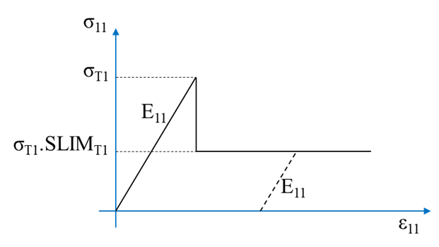
- The
Chang-Chang criteria are given as:
- Tensile Fiber mode:
If , shell element ply is removed if DFAILT =0 or solid element is deleted.
- Compressive Fiber mode:
If , is set to minimum stress limit.
- Tensile Matrix mode:
If , is set to minimum stress limit.
- Compressive Matrix mode:
If , is set to minimum stress limit.
- The original criterion of Hashin in the tensile fiber mode is set with = 1.
- For = 0, you get the maximum stress criterion which is found to compare better to experiments.
- Tensile Fiber mode:
- If the
2WAY fiber flag is set, then the failure criteria for
tensile and compressive fiber failure in the orthotropic 1 direction are
unchanged. For orthotropic direction 2, the same failure criteria as for the
1-direction fibers are used:
- Tensile fiber mode in the orthotropic direction 2:
If , shell element ply is removed if DFAILT =0 or solid element is deleted.
- Compressive fiber mode in the orthotropic direction
2:
If , is set to minimum stress limit.
- Matrix fails only in shear:
If , is set to minimum stress limit.
- Tensile fiber mode in the orthotropic direction 2:
- Integration point failure can occur in three different ways:
- If DFAILT is zero, failure occurs if the Chang-Chang failure criterion is satisfied in the tensile fiber mode.
- If DFAILT is greater than zero, failure occurs
if:
- The fiber strain is greater than DFAILT or less than DFAILC
- If the absolute value of matrix strain is greater than DFAILM
- If the absolute value of tensorial shear strain is greater than DFAILS
- If EFS is greater than zero, failure occurs if the effective strain is greater than EFS.
- Transverse shear strain damage model.
In an optional damage model for transverse shear strain, out-of-plane stiffness (G13 and G23) can linearly decrease to model interlaminar shear failure. Damage starts when effective transverse shear strain reaches EPSF. Final rupture occurs when effective transverse shear strain reaches EPSR.
A maximum damage of TSMD (0.0 < TSMD < 0.99) cannot be exceeded.Figure 2. Linear damage for transverse shear behavior 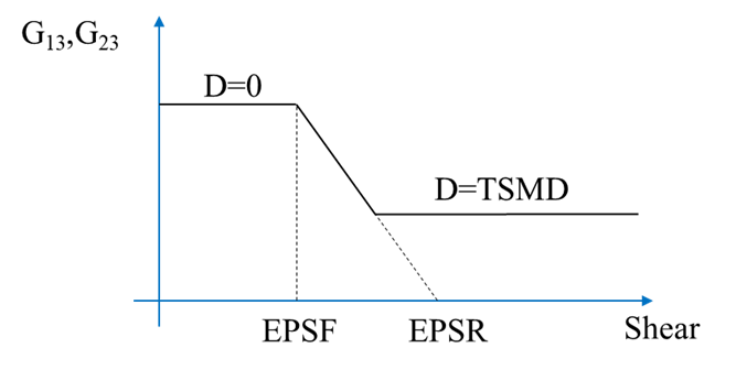
- The flag
TI applies only to transversal isotropic behavior for
material solid elements. the stress/strain relationship is given using the
3D stress/Strain relationship, under the following
conditions:
- Damage
mode value can be display with the output
/H3D/ELEM/DAMG/ID=<mat_ID>/MODE=ALL/… with the
following output:
- Tensile fiber damage
- Compressive tensile damage
- Tension transverse matrix damage
- Compressive transverse matrix damage
- Shear matrix damage