/INTER/TYPE12
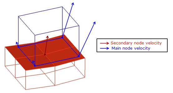
Block Format Keyword Interface TYPE12 described fluid to fluid contact and enables the transmission of flow between two ALE surfaces (main and secondary side). The secondary node velocities are interpolated from main surface values. Then convective fluxes are calculated between the two surfaces.
Description
Format
| (1) | (2) | (3) | (4) | (5) | (6) | (7) | (8) | (9) | (10) |
|---|---|---|---|---|---|---|---|---|---|
| /INTER/TYPE12/inter_ID | |||||||||
| inter_title | |||||||||
| surf_IDs | surf_IDm | Interpol | |||||||
| Tol | |||||||||
| ITIED | Bcopt | skew_ID | node_ID | ||||||
| (1) | (2) | (3) | (4) | (5) | (6) | (7) | (8) | (9) | (10) |
|---|---|---|---|---|---|---|---|---|---|
| XC | YC | ZC | |||||||
| XN | YN | ZN | |||||||
| XT | YT | ZT | |||||||
Definition
| Field | Contents | SI Unit Example |
|---|---|---|
| inter_ID | Interface
identifier. (Integer, maximum 10 digits) |
|
| inter_title | Interface
title. (Character, maximum 100 characters) |
|
| surf_IDs | Secondary surface
identifier. 1
(Integer) |
|
| surf_IDm | Main surface identifier.
1 (Integer) |
|
| Interpol | Interpolation flag. 5
(Integer) |
|
| Tol | Tolerance for segment
search. Default = 0.02 (Real) |
|
| ITIED | Option for surface
connection. 4
(Integer) |
|
| Bcopt | Kinematic constraint
deactivation flag. 6
(Integer) |
|
| skew_ID | Skew system identifier for
polar interpolation. 5 (Integer) |
|
| node_ID | Reference node number for
polar interpolation. 5 (Integer) |
|
| XC | X coordinate of center of
rotation. (Real) |
|
| YC | Y coordinate of center of
rotation. (Real) |
|
| ZC | Z coordinate of center of
rotation. (Real) |
|
| XN | X component of the vector
defining the rotation axis. (Real) |
|
| YN | Y component of the vector
defining the rotation axis. (Real) |
|
| ZN | Z component of the vector
defining the rotation axis. (Real) |
|
| Angle of
rotation. (Real) |
||
| XT | X component of translation
vector. (Real) |
|
| YT | Y component of translation
vector. (Real) |
|
| ZT | Z component of translation
vector. (Real) |
Comments
- Main surface must be coarser or equal to secondary surface. Each main segment needs at least on secondary node on the opposite surface.
- You may act on grid velocities with ALE boundary conditions (/ALE/BCS), ALE links (/VEL/ALE (Obsolete)), or with a porous property (/PROP/TYPE15 (POROUS)) which enable to apply a rigid body motion.
- This interface, like interface TYPE2, is a kinematic condition. No other kinematic condition should be set on any node of the secondary surface.
- ITIED flag sets the connection formulation.
- If ITIED = 0 (free)The algorithm continuously searches for a main segment neighbor corresponding to each secondary node. The node does not need to lie in the segment plane. This is the general case.
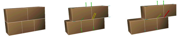
Figure 2. - If ITIED = 1 (tied)The neighbor search is performed initially and the grid velocity is then computed to keep the secondary node on its initial main segment.
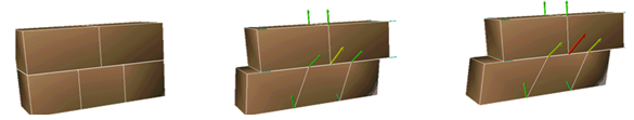
Figure 3. - If ITIED = 2 (periodic)A transformation matrix (translation and rotation defined from lines 6 to 8) is applied to the secondary nodes. Neighbors are then searched as for option ITIED =1. This allows communication between two faces of one or two different domains to reproduce angular periodicity: all material exiting from one side is injected on the other side after rotation.
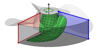
Figure 4. - If ITIED = 3 (no convection)
Only the momentum equation couples the two surfaces and convection of density, energy are inhibited. This can be used to couple one Lagrangian side and a fluid side with meshes remaining independent. The result is normally a one-way coupling. Setting explicitly the modification scale factor fluxes to 1 in the relevant /ALE/MAT will activate two-way coupling.
Except for formulation ITIED = 1 you have to check that the interface nodes are facing the corresponding surface.
- If ITIED = 0 (free)
- For rotating machines, polar
interpolation in perpendicular directions is more accurate.
- If Interpol = 1, you should provide a skew (skew_ID) for rotation axis and a center (node_ID); otherwise the following defaults are used.
- If skew_ID =0, the global x-axis is the polar axis. If a center node is provided (node_ID), it will be treated as the origin of the polar coordinate system, otherwise global origin is used.
- If a skew system is provided, the first axis of the skew is the polar axis. If the skew system type is "moving", the first node given in the skew system is considered; otherwise if defined the center node (node_ID) is the origin, if not defined the global origin (0,0,0) is used.
- This Bcopt
option allows delete secondary nodes in the interface treatment of momentum. The
nodes are deleted if other kinematic conditions are applied, depending on the
flag value.
- Bcopt = 0: Default value set to 2
- Bcopt = 1: No node deleted. Warnings are displayed for nodes, to which other kinematic conditions have been set. This is not recommended, but allowed, as long as the several kinematic conditions result in the same behavior (for example, a secondary node may have fixed b.c.) when it is tied to a fixed main node.
- Bcopt = 2: Secondary nodes will be omitted if they are also secondary of a Lagrange/Lagrange interface (/INTER/LAGMUL/TYPE2) or secondary of a rigid body. Other conflicting kinematic conditions will issue a warning as in option 1.
- Bcopt = 3: Same as option 2; but fully fixed nodes are also omitted.
This option does not affect mass and energy transfer.
- Transformation matrix results from a rotation of angle around axis (XN, YN, and ZN) with center (XC, YC, and ZC), followed by a translation (XT, YT, and ZT).
- This interface is not compatible with ALE multi-material LAW37 and LAW51.