
RD-V: 0310 /GRAV versus /IMPACC
Ball is falling and hits the ground under /GRAV and /IMPACC loads to compare its response.
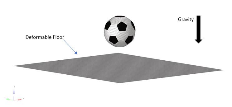
The analysis shows the behavior of a ball that falls and impacts the ground.
The ball (200mm diameter) is modeled with an elastic orthotropic material (/MAT/LAW19), a control volume (/MONVOL/AIRBAG1) and internal spring elements.
- With a load with /GRAV card image and constant value equal to -9810 mm/s2
- With a load with /IMPACC card image and constant value equal to -9810 mm/s2
The ball kinematics are extracted based on a node on ball surface, and the different energy values are used to explain what happens when using each type of load.
Options and Keywords
- Materials:
- Properties:
- Elements:
- Loads:
- Curves:
- Sets:
Model Files
Model Description
Units: g, ms, mm, MPa
To model the ball, shell elements (/SHELL and /SH3N) have been used and assigned with a fabric elastic orthotropic material law (/MAT/FABRI). In addition, a controlled volume (/MONVOL/AIRBAG1) is created to keep the pressure inside the ball constant during the simulation.
The only loads that are applied to the ball are /GRAV or /IMPACC, one in each model. This is also the only change between the models provided. The target acceleration value is 0.00981 mm/msec2 (or 9.81 m/s2).
The floor part is considered to be deformable, whereby the boundary nodes are constrained in all the degrees of freedom.
Finally, a linear contact interface is created (/INTER/TYPE24) to model the interaction between floor and ball.
The ball is dropped with an initial velocity of zero and its kinematics are captured using a surface node.
Results
As you can see, in the first situation (/GRAV), the contact force causes the ball to bounce on the floor, while in the second situation (/IMPACC), the movement of the ball is not affected by the contact force but causes a large deformation of the floor.
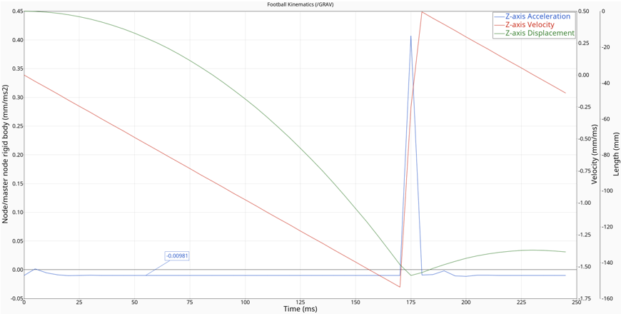
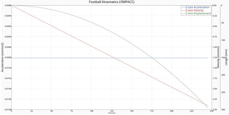
Figure 3 shows that the value of acceleration is only constant to gravity acceleration (0.00981 mm/msec2) if gravity is the only force applied to the ball. Between 170 and 200 msec the acceleration changes rapidly due to the contact. Additionally, the acceleration value is not preserved in the first 20 msec because of the initialization of the control volume. On the other hand, as Figure 4 shows that the imposed acceleration does not give the ball a different acceleration value during the entire simulation time. To achieve this, external forces are applied to the system in such a way that the acceleration of the ball is preserved.
Specifically, in Figure 4 the ball follows the equations of free fall with an initial velocity of zero. These equations for displacement and velocity are explained below.
and
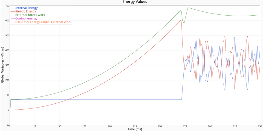
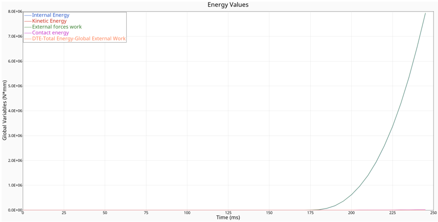
Figure 6 clearly shows that after the ball contacts the floor, a large amount of external force is applied to the model to preserve the acceleration value and as a result deform the floor part.
To summarize, gravity (/GRAV) and imposed acceleration (/IMPACC) loads have a completely different scope and different way of application, even if they can lead to the same results in some cases. The former is a specific force, while the latter is a kinematic condition.