/DFS/WAV_SHA
Block Format Keyword Detonation times are computed taking into account an obstacle. The boundary of the obstacle is provided with an ordered group of nodes which defines the screen lines.
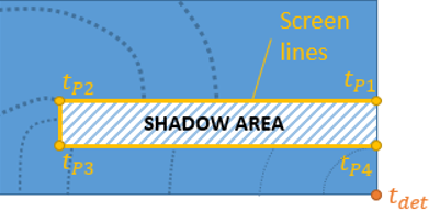
Figure 1.
Format
| (1) | (2) | (3) | (4) | (5) | (6) | (7) | (8) | (9) | (10) |
|---|---|---|---|---|---|---|---|---|---|
| /DFS/WAV_SHA/detline_ID/unit_ID | |||||||||
| VDET | YDET | ZDET | TDET | mat_IDDET | grnod_ID | ||||
Definition
| Field | Contents | SI Unit Example |
|---|---|---|
| detline_ID | Detonation Line identifier. (Integer, maximum 10 digits) |
|
| unit_ID | Unit Identifier (Integer, maximum 10 digits) |
|
| VDET | Optional: Detonation Velocity from
detonation point. 8
(Real) |
|
| YDET | Y coordinate. (Real) |
|
| ZDET | Z coordinate. (Real) |
|
| TDET | Detonation time. Default = 0.0 (Real) |
|
| mat_IDDET | Explosive material number concerned by
detonation time.
(Integer) |
|
| grnod_ID | Unsortable node group identifier. 1
2 Default = 0 (Integer) |
Comments
- Node path must be provided in the correct order through an unsortable node group identifier (/GRNOD/NODENS). It defines the screen lines.
- Detonation times are available in the Starter output file (IPRI ≥ 3). Each element detonation time is computed at its centroid.
- Burn fractions are available in the time history file with /TH/BRIC card and BFRAC keyword.
- Detonation velocity is collected from the /MAT/LAW5 (JWL).
- Only compatible with 2D modeling.
- From an algorithm point of view, all points from the screen lines are considered
as a potential detonation origin. The shortest detonation time is retained within all
sources which have a direct path (if path from a potential source crosses any screen line
then this source is ignored).
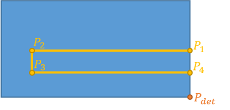
Figure 2. Screen Lines are defined into an ordered group of nodesDetonation times are computed for each screen point by calculating the length of the path starting from detonation point.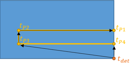
Figure 3.Screen points are considered as a potential detonation source (spherical). An arrival time is computed from each screen point, unless the direct path to the target point is intersected by a screen line.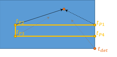
Figure 4.
Figure 5. Shortest time is retained as the detonation time - Detonation times for each element are then sent to the Engine as an initial condition. It may evolve with time due to rezoning (if unreacted explosive moves into the ALE grid or if the ALE grid used to model the unreacted explosive is moving).
- When a direct path exists from
detonation point (element centroid or screen point), it is then lit using velocity
VDET. Otherwise, detonation velocity is
read form material with identifier mat_ID. This makes detonation of two adjacent explosives possible.
Figure 6. Two adjacent explosive materials with two different detonation velocities
Figure 7. Detonation times are computed with different detonation velocities in each side of the screen lines