Block Format Keyword Describes the standard formulation for ALE grid
velocity computation.
It is an improved
/ALE/GRID/SPRING formulation based on edge springs
and anti-shear springs.
1
Figure 1.
Format
(1)
(2)
(3)
(4)
(5)
(6)
(7)
(8)
(9)
(10)
/ALE/GRID/STANDARD
α
γ
η
l
c
MathType@MTEF@5@5@+=
feaagKart1ev2aqatCvAUfeBSjuyZL2yd9gzLbvyNv2CaerbuLwBLn
hiov2DGi1BTfMBaeXatLxBI9gBaerbd9wDYLwzYbItLDharqqtubsr
4rNCHbGeaGqiVu0Je9sqqrpepC0xbbL8F4rqqrFfpeea0xe9Lq=Jc9
vqaqpepm0xbba9pwe9Q8fs0=yqaqpepae9pg0FirpepeKkFr0xfr=x
fr=xb9adbaqaaeGaciGaaiaabeqaamaabaabaaGcbaGaamiBamaaBa
aaleaacaWGJbaabeaaaaa@37FC@
Blank Format
Definition
Field
Contents
SI Unit Example
α
Scale factor for maximum stiffness.
2
Default = 0.9 (Real)
γ
Nonlinearity factor for edge spring
stiffness. 3 Default = 1e-2 (Real)
η
Damping coefficient. 4 Default = 1e-2 (Real)
l
c
MathType@MTEF@5@5@+=
feaagKart1ev2aqatCvAUfeBSjuyZL2yd9gzLbvyNv2CaerbuLwBLn
hiov2DGi1BTfMBaeXatLxBI9gBaerbd9wDYLwzYbItLDharqqtubsr
4rNCHbGeaGqiVu0Je9sqqrpepC0xbbL8F4rqqrFfpeea0xe9Lq=Jc9
vqaqpepm0xbba9pwe9Q8fs0=yqaqpepae9pg0FirpepeKkFr0xfr=x
fr=xb9adbaqaaeGaciGaaiaabeqaamaabaabaaGcbaGaamiBamaaBa
aaleaacaWGJbaabeaaaaa@37FC@
Characteristic
length.(Real)
[
m
]
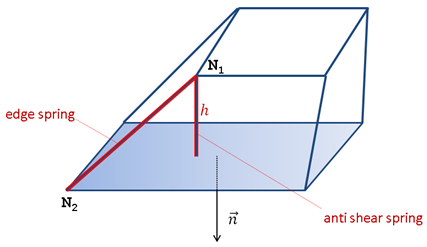
Comments Fictitious springs are introduced on solid elements to control grid
velocities.These springs are nonlinear elastic viscous. To ensure stability, their
stiffness is computed from time step. The two types of springs are edge and anti-shear
springs.
Edge springsThe forces for an edge spring are a function of its length variation
during time.
(1)
Δ
F
e
d
g
e
=
k
(
h
)
⋅
(
w
2
−
w
1
)
d
t
Where,
w
1
,
w
2
MathType@MTEF@5@5@+=
feaagKart1ev2aqatCvAUfeBSjuyZL2yd9gzLbvyNv2CaerbuLwBLn
hiov2DGi1BTfMBaeXatLxBI9gBaerbd9wDYLwzYbItLDharqqtubsr
4rNCHbGeaGqiVu0Je9sqqrpepC0xbbL8F4rqqrFfpeea0xe9Lq=Jc9
vqaqpepm0xbba9pwe9Q8fs0=yqaqpepae9pg0FirpepeKkFr0xfr=x
fr=xb9adbaqaaeGaciGaaiaabeqaamaabaabaaGcbaGaaC4DamaaBa
aaleaacaaIXaaabeaakiaacYcacaWH3bWaaSbaaSqaaiaaikdaaeqa aaaa@3A80@
are grid velocities on nodes
N 1 and N 2 ,
respectively.
h
is the N 1 distance
from opposite face
d
t
is the time step
and
k
(
h
)
is the spring stiffness
k
(
h
)
=
k
c
r
i
t
i
c
a
l
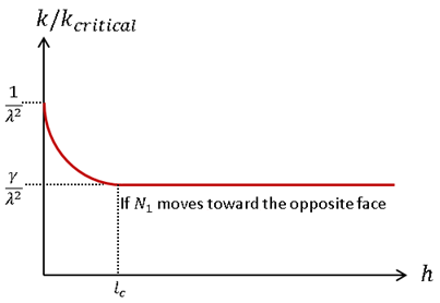
If
h
is inferior to the characteristic length
l
c
and
N 1 is moving
toward the opposite face then,
(2)
k
(
h
)
=
1
λ
2
[
γ
+
(
γ
−
1
)
(
h
−
l
c
l
c
)
3
]
k
c
r
i
t
i
c
a
l
1
λ
2
MathType@MTEF@5@5@+=
feaagKart1ev2aaatCvAUfeBSjuyZL2yd9gzLbvyNv2CaerbuLwBLn
hiov2DGi1BTfMBaeXatLxBI9gBaerbd9wDYLwzYbItLDharqqtubsr
4rNCHbGeaGqiVu0Je9sqqrpepC0xbbL8F4rqqrFfpeea0xe9Lq=Jc9
vqaqpepm0xbba9pwe9Q8fs0=yqaqpepae9pg0FirpepeKkFr0xfr=x
fr=xb9adbaqaaeGaciGaaiaabeqaamaabaabaaGcbaWaaSGaaeaaca
aIXaaabaGaeq4UdW2aaWbaaSqabeaacaaIYaaaaaaaaaa@3960@
is the stability factor taking into account the damping factor
β
, the scale factor
α
, and time step
d
t
4
Figure 2.
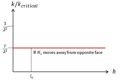
otherwise,
k
(
h
)
=
γ
λ
2
k
c
r
i
t
i
c
a
l
MathType@MTEF@5@5@+=
feaagKart1ev2aqatCvAUfeBSjuyZL2yd9gzLbvyNv2CaerbuLwBLn
hiov2DGi1BTfMBaeXatLxBI9gBaerbd9wDYLwzYbItLDharqqtubsr
4rNCHbGeaGqiVu0Je9sqqrpepC0xbbL8F4rqqrFfpeea0xe9Lq=Jc9
vqaqpepm0xbba9pwe9Q8fs0=yqaqpepae9pg0FirpepeKkFr0xfr=x
fr=xb9adbaqaaeGaciGaaiaabeqaamaabaabaaGcbaGaci4Aamaabm
aabaGaamiAaaGaayjkaiaawMcaaiabg2da9maalaaabaGaeq4SdCga
baGaeq4UdW2aaWbaaSqabeaacaaIYaaaaaaakiaadUgadaWgaaWcba
Gaam4yaiaadkhacaWGPbGaamiDaiaadMgacaWGJbGaamyyaiaadYga aeqaaaaa@4751@
Figure 3.
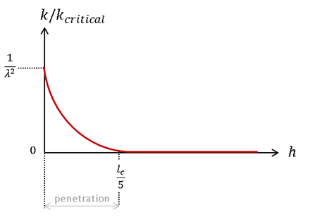
Anti-shear springsThe anti-shear forces
F
s
h
e
a
r
MathType@MTEF@5@5@+=
feaagKart1ev2aqatCvAUfeBSjuyZL2yd9gzLbvyNv2CaerbuLwBLn
hiov2DGi1BTfMBaeXatLxBI9gBaerbd9wDYLwzYbItLDharqqtubsr
4rNCHbGeaGqiVu0Je9sqqrpepC0xbbL8F4rqqrFfpeea0xe9Lq=Jc9
vqaqpepm0xbba9pwe9Q8fs0=yqaqpepae9pg0FirpepeKkFr0xfr=x
fr=xb9adbaqaaeGaciGaaiaabeqaamaabaabaaGcbaGaaCOramaaBa
aaleaacaWGZbGaamiAaiaadwgacaWGHbGaamOCaaqabaaaaa@3B9E@
are computed from node penetration. gap is
l
c
s
MathType@MTEF@5@5@+=
feaagKart1ev2aqatCvAUfeBSjuyZL2yd9gzLbvyNv2CaerbuLwBLn
hiov2DGi1BTfMBaeXatLxBI9gBaerbd9wDYLwzYbItLDharqqtubsr
4rNCHbGeaGqiVu0Je9sqqrpepC0xbbL8F4rqqrFfpeea0xe9Lq=Jc9
vqaqpepm0xbba9pwe9Q8fs0=yqaqpepae9pg0FirpepeKkFr0xfr=x
fr=xb9adbaqaaeGaciGaaiaabeqaamaabaabaaGcbaWaaSGaaeaaca
WGSbWaaSbaaSqaaiaadogaaeqaaaGcbaGaam4Caaaaaaa@3910@
from opposite face.
The value of
F
s
h
e
a
r
MathType@MTEF@5@5@+=
feaagKart1ev2aqatCvAUfeBSjuyZL2yd9gzLbvyNv2CaerbuLwBLn
hiov2DGi1BTfMBaeXatLxBI9gBaerbd9wDYLwzYbItLDharqqtubsr
4rNCHbGeaGqiVu0Je9sqqrpepC0xbbL8F4rqqrFfpeea0xe9Lq=Jc9
vqaqpepm0xbba9pwe9Q8fs0=yqaqpepae9pg0FirpepeKkFr0xfr=x
fr=xb9adbaqaaeGaciGaaiaabeqaamaabaabaaGcbaGaaCOramaaBa
aaleaacaWGZbGaamiAaiaadwgacaWGHbGaamOCaaqabaaaaa@3B9E@
is:
(3)
F
s
h
e
a
r
=
g
a
p
⋅
k
(
h
)
MathType@MTEF@5@5@+=
feaagKart1ev2aqatCvAUfeBSjuyZL2yd9gzLbvyNv2CaerbuLwBLn
hiov2DGi1BTfMBaeXatLxBI9gBaerbd9wDYLwzYbItLDharqqtubsr
4rNCHbGeaGqiVu0Je9sqqrpepC0xbbL8F4rqqrFfpeea0xe9Lq=Jc9
vqaqpepm0xbba9pwe9Q8fs0=yqaqpepae9pg0FirpepeKkFr0xfr=x
fr=xb9adbaqaaeGaciGaaiaabeqaamaabaabaaGcbaGaaCOramaaBa
aaleaacaWGZbGaamiAaiaadwgacaWGHbGaamOCaaqabaGccqGH9aqp
caWGNbGaamyyaiaadchacqGHflY1ciGGRbWaaeWaaeaacaWGObaaca
GLOaGaayzkaaaaaa@4526@
and
(4)
k
(
h
)
=
γ
λ
2
[
γ
+
(
γ
−
1
)
(
h
−
l
c
l
c
)
3
]
k
c
r
i
t
i
c
a
l
MathType@MTEF@5@5@+=
feaagKart1ev2aqatCvAUfeBSjuyZL2yd9gzLbvyNv2CaerbuLwBLn
hiov2DGi1BTfMBaeXatLxBI9gBaerbd9wDYLwzYbItLDharqqtubsr
4rNCHbGeaGqiVu0Je9sqqrpepC0xbbL8F4rqqrFfpeea0xe9Lq=Jc9
vqaqpepm0xbba9pwe9Q8fs0=yqaqpepae9pg0FirpepeKkFr0xfr=x
fr=xb9adbaqaaeGaciGaaiaabeqaamaabaabaaGcbaGaci4Aamaabm
aabaGaamiAaaGaayjkaiaawMcaaiabg2da9maalaaabaGaeq4SdCga
baGaeq4UdW2aaWbaaSqabeaacaaIYaaaaaaakmaadmaabaGaeq4SdC
Maey4kaSYaaeWaaeaacqaHZoWzcqGHsislcaaIXaaacaGLOaGaayzk
aaWaaeWaaeaadaWcaaqaaiaadIgacqGHsislcaWGSbWaaSbaaSqaai
aadogaaeqaaaGcbaGaamiBamaaBaaaleaacaWGJbaabeaaaaaakiaa
wIcacaGLPaaadaahaaWcbeqaaiaaiodaaaaakiaawUfacaGLDbaaca
WGRbWaaSbaaSqaaiaadogacaWGYbGaamyAaiaadshacaWGPbGaam4y
aiaadggacaWGSbaabeaaaaa@5929@
Figure 4.
Viscous DampingViscous forces are computed from a critical damping corresponding
to the upper bound for stiffness:
1
λ
2
MathType@MTEF@5@5@+=
feaagKart1ev2aqatCvAUfeBSjuyZL2yd9gzLbvyNv2CaerbuLwBLn
hiov2DGi1BTfMBaeXatLxBI9gBaerbd9wDYLwzYbItLDharqqtubsr
4rNCHbGeaGqiVu0Je9sqqrpepC0xbbL8F4rqqrFfpeea0xe9Lq=Jc9
vqaqpepm0xbba9pwe9Q8fs0=yqaqpepae9pg0FirpepeKkFr0xfr=x
fr=xb9adbaqaaeGaciGaaiaabeqaamaabaabaaGcbaWaaSGaaeaaca
aIXaaabaGaeq4UdW2aaWbaaSqabeaacaaIYaaaaaaaaaa@3961@
(5)
F
v
i
s
c
o
u
s
=
β
α
(
1
+
β
2
−
β
)
(
w
2
−
w
1
)
MathType@MTEF@5@5@+=
feaagKart1ev2aqatCvAUfeBSjuyZL2yd9gzLbvyNv2CaerbuLwBLn
hiov2DGi1BTfMBaeXatLxBI9gBaerbd9wDYLwzYbItLDharqqtubsr
4rNCHbGeaGqiVu0Je9sqqrpepC0xbbL8F4rqqrFfpeea0xe9Lq=Jc9
vqaqpepm0xbba9pwe9Q8fs0=yqaqpepae9pg0FirpepeKkFr0xfr=x
fr=xb9adbaqaaeGaciGaaiaabeqaamaabaabaaGcbaGaaCOramaaBa
aaleaacaWG2bGaamyAaiaadohacaWGJbGaam4BaiaadwhacaWGZbaa
beaakiabg2da9iabek7aIjabeg7aHnaabmaabaWaaOaaaeaacaaIXa
Gaey4kaSIaeqOSdi2aaWbaaSqabeaacaaIYaaaaaqabaGccqGHsisl
cqaHYoGyaiaawIcacaGLPaaadaqadaqaaiaahEhadaWgaaWcbaGaaG
OmaaqabaGccqGHsislcaWH3bWaaSbaaSqaaiaaigdaaeqaaaGccaGL
OaGaayzkaaaaaa@50A2@
Grid VelocityThe grid velocity is then updated according to:
(6)
w
n
+
1
=
w
n
+
(
Δ
F
e
d
g
e
+
F
s
h
e
a
r
+
F
v
i
s
c
o
u
s
)
d
t
m
Where,
m
is fictitious mass on node from springs (automatically
computed during Starter).
Increasing
α
=
1
, the maximum stiffness will be increased. The scale factor
α
determines the maximum stiffness for a given spring at zero
length. The scale factor ensures that the critical stability value is not exceeded (to avoid
time step decrease).
This flag is acting on stiffness
shape. Stiffness is linear with
γ
= 0 . Moreover, increasing
γ
, the lower bound stiffness for edge spring will be increased. Springs
have a critical stiffness at zero length (this corresponds to a unitary factor). For a
length greater than or equal to the characteristic length, the spring stiffness is the
critical stiffness multiplied by
γ
.
It is recommended to use small
values for
β
, otherwise damping may become over critical. The stability factor
is:(7)
λ
=
d
t
α
0
(
1
+
β
2
−
β
)
MathType@MTEF@5@5@+=
feaagKart1ev2aqatCvAUfeBSjuyZL2yd9gzLbvyNv2CaerbuLwBLn
hiov2DGi1BTfMBaeXatLxBI9gBaerbd9wDYLwzYbItLDharqqtubsr
4rNCHbGeaGqiVu0Je9sqqrpepC0xbbL8F4rqqrFfpeea0xe9Lq=Jc9
vqaqpepm0xbba9pwe9Q8fs0=yqaqpepae9pg0FirpepeKkFr0xfr=x
fr=xb9adbaqaaeGaciGaaiaabeqaamaabaabaaGcbaGaeq4UdWMaey
ypa0ZaaSaaaeaacaWGKbGaamiDaaqaaiabeg7aHnaaBaaaleaacaaI
WaaabeaakmaabmaabaWaaOaaaeaacaaIXaGaey4kaSIaeqOSdi2aaW
baaSqabeaacaaIYaaaaaqabaGccqGHsislcqaHYoGyaiaawIcacaGL Paaaaaaaaa@458A@
l
c
MathType@MTEF@5@5@+=
feaagKart1ev2aqatCvAUfeBSjuyZL2yd9gzLbvyNv2CaerbuLwBLn
hiov2DGi1BTfMBaeXatLxBI9gBaerbd9wDYLwzYbItLDharqqtubsr
4rNCHbGeaGqiVu0Je9sqqrpepC0xbbL8F4rqqrFfpeea0xe9Lq=Jc9
vqaqpepm0xbba9pwe9Q8fs0=yqaqpepae9pg0FirpepeKkFr0xfr=x
fr=xb9adbaqaaeGaciGaaiaabeqaamaabaabaaGcbaGaamiBamaaBa
aaleaacaWGJbaabeaaaaa@37FC@
defines the length below which:
Edge spring stiffness is increased
h
<
l
c
MathType@MTEF@5@5@+=
feaagKart1ev2aqatCvAUfeBSjuyZL2yd9gzLbvyNv2CaerbuLwBLn
hiov2DGi1BTfMBaeXatLxBI9gBaerbd9wDYLwzYbItLDharqqtubsr
4rNCHbGeaGqiVu0Je9sqqrpepC0xbbL8F4rqqrFfpeea0xe9Lq=Jc9
vqaqpepm0xbba9pwe9Q8fs0=yqaqpepae9pg0FirpepeKkFr0xfr=x
fr=xb9adbaqaaeGaciGaaiaabeqaamaabaabaaGcbaGaamiAaiabgY
da8iaadYgadaWgaaWcbaGaam4yaaqabaaaaa@39ED@
Anti-shear spring is activated:
h
<
l
c
5
MathType@MTEF@5@5@+=
feaagKart1ev2aqatCvAUfeBSjuyZL2yd9gzLbvyNv2CaerbuLwBLn
hiov2DGi1BTfMBaeXatLxBI9gBaerbd9wDYLwzYbItLDharqqtubsr
4rNCHbGeaGqiVu0Je9sqqrpepC0xbbL8F4rqqrFfpeea0xe9Lq=Jc9
vqaqpepm0xbba9pwe9Q8fs0=yqaqpepae9pg0FirpepeKkFr0xfr=x
fr=xb9adbaqaaeGaciGaaiaabeqaamaabaabaaGcbaGaamiAaiabgY
da8maaliaabaGaamiBamaaBaaaleaacaWGJbaabeaaaOqaaiaaiwda aaaaaa@3AC8@
All these parameters can be
modified during an Engine restart (/ALE/GRID/STANDARD ).
Mesh auto correction. It is
possible to give more weight to anti-shear forces by either:
Setting
l
c
MathType@MTEF@5@5@+=
feaagKart1ev2aqatCvAUfeBSjuyZL2yd9gzLbvyNv2CaerbuLwBLn
hiov2DGi1BTfMBaeXatLxBI9gBaerbd9wDYLwzYbItLDharqqtubsr
4rNCHbGeaGqiVu0Je9sqqrpepC0xbbL8F4rqqrFfpeea0xe9Lq=Jc9
vqaqpepm0xbba9pwe9Q8fs0=yqaqpepae9pg0FirpepeKkFr0xfr=x
fr=xb9adbaqaaeGaciGaaiaabeqaamaabaabaaGcbaGaamiBamaaBa
aaleaacaWGJbaabeaaaaa@37FC@
parameter close to the mesh size
Setting a negative value for
α
parameter (elastic forces on edges are set to 0 at the
first cycle of current run)
This method assumes a homogeneous
spring repartition around each node. This is not the case when connecting two meshes, where
topologies are different.