OS-T: 6040 Spot Weld Fatigue using S-N Method
In this tutorial an additional subcase will be created to calculate the Spot Weld Fatigue by the RUPP method.
Spot weld fatigue can only be applied to spot welds between two shells. The spot weld location is defined by three attributes, sheet 1, sheet 2, and the nugget. The sheets are defined by shell elements, and the nugget is defined by CWELD, CBAR, CBEAM, or CHEXA elements. The nugget can be directly connected to the shells or RBE2/RBE3 elements can be used to connect the nugget to the shells.
Two sections are held together by spot welds. Like the fillet weld tutorial, an additional subcase will be created to calculate the Spot Weld Fatigue by the RUPP method.
Launch HyperMesh and Set the OptiStruct User Profile
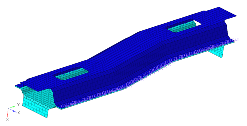
The model being used for this exercise is that of an automotive frame (OS-T: 6040 Spot Weld Fatigue using S-N Method). The input file consists of 3 static loadsteps to which the frame is subjected to – Frontal torsion, Rear torsion and the Vertical bending.
-
Launch HyperMesh.
The User Profile dialog opens.
-
Select OptiStruct and click
OK.
This loads the user profile. It includes the appropriate template, macro menu, and import reader, paring down the functionality of HyperMesh to what is relevant for generating models for OptiStruct.
Import the Model
-
Click .
An Import tab is added to your tab menu.
- For the File type, select OptiStruct.
-
Select the Files icon
 .
A Select OptiStruct file browser opens.
.
A Select OptiStruct file browser opens. - Select the Spotweld_CbarNugget.fem file you saved to your working directory.
- Click Open.
-
Click Import, then click Close to
close the Import tab.
The outline of the Fatigue Analysis setup to be achieved in the following steps.
Figure 2. Fatigue Setup – Spot Welds 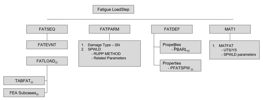
Set Up the Model
Define TABFAT Load Collector
- Make sure the Utility menu is selected in the View menu. Click .
- Click on the Utility menu beside the Model tab in the browser. In the Tools section, click on TABLE Create.
- Set Options to Import table.
- Set Tables to TABFAT.
- Click Next.
- Browse for the loading file.
- In the Open the XY Data File dialog box, set the Files of type filter to CSV (*.csv).
- Open the load1.csv file you saved to your working directory.
- Create New Table with Name LH1.
-
Click Apply to save the table.
The curve LH1 with TABFAT card image is created.
-
Click Apply to save the table.
The load collector table2 with TABFAT card image is created.
-
Exit from the Import TABFAT window.
Tables appear under Load Collector in the Model Browser.Note: A file in DAC format can very easily be imported in HyperGraph and converted to CSV format to be read in HyperMesh.
Define FATLOAD Load Collector
Create a fatload each for the loadcases present.
- In the Model Browser, right-click and select .
- For Name, enter Fatload_Front.
- For Card Image, select FATLOAD.
- For TID(table ID), select LH1 from the list of curves.
- For LCID (load case ID), select Front Torsional Stiffness from the list of load steps.
- Set LDM (load magnitude) to 0.1.
- Set Scale to 3.0.
-
Repeat the process to create 2 additional load collectors with
FATLOAD cards named:
Fatload_Rear with LCID as Rear Torsional Stiffness and TID as LH1
Fatload_Vertical with LCID as Vertical Bending Stiffness and TID as LH1
- Set LDM to 0.1 and Scale to 3.0.
Define FATEVNT Load Collector
Create an event to assign the fatloads created.
- In the Model Browser, right-click and select .
- For Name, enter Event1.
- For Card Image, select FATEVNT.
- For FATEVNT_NUM_FLOAD, enter 3.
-
Click on the Table icon
 next to the Data
field and select the 3 FLOAD load collectors
created.
next to the Data
field and select the 3 FLOAD load collectors
created.
Figure 3. Event Card 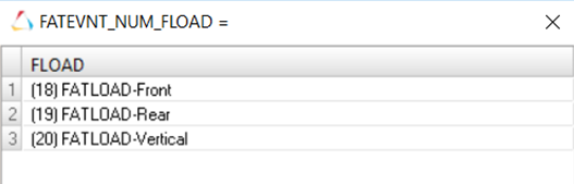
Define FATSEQ Load Collector
- In the Model Browser, right-click and select .
- For Name, enter Fat-Sequence.
- For Card Image, select FATSEQ.
- For FATSEQ_NUM enter 1, as 1 FATEVENT has been created.
-
For FID (Fatigue Event Definition), select Event1
and N as
1.
Tip: Right-click on N and select Status to edit.Defining the sequence of events for the fatigue analysis is completed. The Fatigue parameters are defined next.
Define Fatigue Parameters
- In the Model Browser, right-click and select .
- For Name, enter Fat-Parameter.
- For Card Image, select FATPARM.
- Verify TYPE is set to SN.
- Set STRESSU to MPA (Stress Units).
- Set RAINFLOW RTYPE to LOAD.
- Set GATEREL to 0.0.
- Set CERTNTY SURVCERT to 0.5.
-
Check the box beside SPWLD and select the following options:
METHOD = RUPP
UCORRECT = FKM
SURVCERT = 0.9
THCKCORR = YES
NANGLE = 20
Define Fatigue Material Properties
The material curve for the fatigue analysis can be defined on the MAT1 card.
-
In the Model Browser, click on the Steel material.
The Entity Editor opens.
- In the Entity Editor, set MATFAT to SN.
- Set UTS (ultimate tensile stress) to 1000.0.
- Check the box besides SPWLD and select the following options.
-
For the SN curve set (these values should be obtained from the material's SN
curve).
- SRI1_SP1
- 1903.0
- B1_SP1
- -0.123
- NC1_SP1
- 1e6
- SE_SP1
- 1
- SRI1_SP2
- 1903.0
- B1_SP2
- -0.123
- NC1_SP2
- 1e6
- SE_SP2
- 1
- SRI1_SP3
- 1903.0
- B1_SP3
- -0.123
- NC1_SP3
- 1e6
- SE_SP3
- 1
Three SN curve details are listed, where 1 = sheet1, 2 = sheet2, 3 = weld nugget.
Define PFATSPW Property
- In the Model Browser, right-click and select .
- For Name, enter PFATSPW.
- For Card Image, select PFATSPW.
- Set SPTFAIL to All.
- Set ALPHA to 3.5.
- Set TREF to 1.0.
- Set TREF_N to 0.2.
- Set SF to 1.0.
- Click Close.
Define FATDEF Load Collector
- In the Model Browser, right-click and select .
- For Name, enter FATDEF1.
- Set the Card Image to FATDEF.
- Activate PTYPE, PBARL and PFATSPWID in the PTYPE Entity Editor.
- For FATDEF_PBARL_NUMIDS, enter 1.
-
Select PBARL_4 for PID and
PFATSPW for PFATSPW.
Figure 4. Fatigue Definition showing the combination of Weld Element Properties 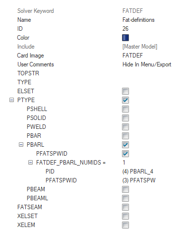
- Click Close.
Define the Fatigue Load Step
- In the Model Browser, right-click and select .
- For Name, enter Fatigue-SpotWeld-Analysis.
- Set the Analysis type to fatigue.
- For FATDEF, select fatdef.
- For FATPARM, select fatparam.
- For FATSEQ, select fatseq.
- Scroll down and check on OUTPUT in SUBCASE OPTIONS and select RNFLOW to output the rainflow count as *.rnf file in the working directory, this file lists the Rainflow calculated for each element.
Submit the Job
- From the Analysis page, enter the OptiStruct panel.
-
Click save as following the input file field.
The Save As dialog opens.
- For File name, enter the name SpotWeld_Cbar_Nugget.fem.
- Click Save.
- Click OptiStruct to submit the analysis.
Review the Results
-
From the OptiStruct panel, click HyperView.
HyperView is launched and the results are loaded. A message window appears to inform of the successful model and result files loading into HyperView.
- Go to the Results tab.
- In the Results tab, select Subcase 4 (Fatigue-SpotWeld-Analysis) from the subcase field.
-
On the Results toolbar, click
 to open the
Contour panel.
to open the
Contour panel.
-
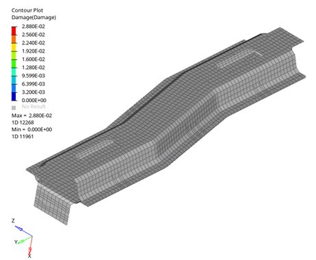
Set Result type to Damage and click on
Apply to contour the elements.
Figure 5. Fatigue Definition showing the combination of Weld Element Properties 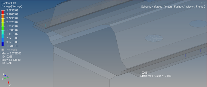
Figure 6. Fatigue Definition showing the combination of Weld Element Properties