OS-T: 6070 Random Response Fatigue Analysis (EN Fatigue)
The study of Fatigue life of a structure subjected to non-deterministic loads.
Power spectral density (PSD) from the Random Response Analysis are used to calculate Moments that are used to generate the probability density function for the number of cycles versus the stress range.
Launch HyperMesh and Set the OptiStruct User Profile
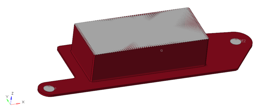
The model being used for this exercise is that of a simple CAD box (Figure 1). Four loadsteps have already been defined on this model, each of which represent Normal Modes Analysis, Frequency Response at both the constraint points and the Random Response Analysis.
-
Launch HyperMesh.
The User Profile dialog opens.
-
Select OptiStruct and click
OK.
This loads the user profile. It includes the appropriate template, macro menu, and import reader, paring down the functionality of HyperMesh to what is relevant for generating models for OptiStruct.
Import the Model
-
Click .
An Import tab is added to your tab menu.
- For the File type, select OptiStruct.
-
Select the Files icon
 .
A Select OptiStruct file browser opens.
.
A Select OptiStruct file browser opens. - Select the CAD-box-eN.fem file you saved to your working directory.
- Click Open.
-
Click Import, then click Close to
close the Import tab.
The outline of the Fatigue Analysis setup to be achieved in the following steps.
Figure 2. Fatigue Setup Random – EN Damage 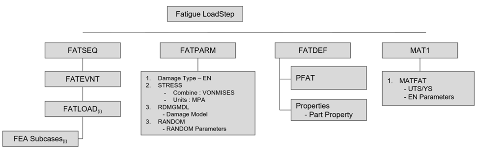
Set Up the Model
Define FATLOAD Load Collector
The model has a Random Response loadstep defined by the RANDPS card. The RANDPS card contains the two input PSD (AutoPSD_A and AutoPSD_B) applied at the constrained locations and the cross PSD (CrossPSD_AB) between them.
- In the Model Browser, right-click and select .
- For Name, enter FATLOAD_RANDOM.
- For Card Image, select FATLOAD.
-
For LCID(load case ID), select Random
Response from
the list of load steps.
Note: TABFAT and scaling parameters are not required for this calculation.
Define FATEVNT Load Collector
Create a random response event for the FATLOAD_RAND created.
- In the Model Browser, right-click and select .
- For Name, enter EVENT_RANDOM.
- For Card Image, select FATEVNT.
- For FATEVNT_NUM_FLOAD, enter 1.
-
Click on the Table icon
 next to the Data
field and select FATLOAD_RANDOM for FLOAD in the pop-out
window.
next to the Data
field and select FATLOAD_RANDOM for FLOAD in the pop-out
window.
Define FATSEQ Load Collector
- In the Model Browser, right-click and select .
- For Name, enter FATSEQ.
- For Card Image, select FATSEQ.
- For FATSEQ_NUM enter 1, as 1 FATEVENT has been created.
-
For FID (Fatigue Event Definition), select EVENT_RANDOM
and N as
1.
Figure 3. FATSEQ showing RAND_EVENT created 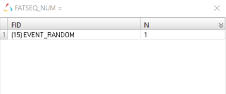
Defining the sequence of events for the fatigue analysis is completed. The Fatigue parameters are defined next.
Define Fatigue Parameters
- In the Model Browser, right-click and select .
- For Name, enter Fat-Parameter.
- For Card Image, select FATPARM.
- Verify TYPE is set to EN.
- Set UCORRECT to NONE.
- Set STRESS COMBINE to VONMISES.
- Set CERTNTY SURVCERT to 0.9.
-
Set RNDPDF as:
DM1 = DIRLINK
DM2 = LALANNE
DM3 = NARROW
-
Check the Random option under RANDOM and edit the
following options:
FACSREND = 8.0 (Calculates the upper limit of the stress range (SREND))
NBIN = 100 (Calculates the width of the range ( S) of stress ranges for which the probability is calculated)
Figure 4. Probability Density Function. (probability density of number of cycles versus stress range) 
Define Fatigue Material Properties
The material curve for the fatigue analysis can be defined on the MAT1 card.
-
In the Model Browser, click on the MAT1 material.
The Entity Editor opens.
- In the Entity Editor, set MATFAT to EN.
- Set UTS (ultimate tensile stress) to 110.
-
For the EN curve set (these values should be
obtained from the material's EN curve):
- SF
- 166.0
- B
- -0.096
- C
- -0.669
- EF
- 1.643
- NP
- 0.144
- KP
- 154.0
- NC
- 2E+06
- SEE
- 0.300
- SEP
- 0.300
- A/R
- A
Define PFAT Load Collector
- In the Model Browser, right-click and select .
- For Name, enter Surface_Treatment.
- For Card Image, select PFAT.
- Set LAYER to WORST.
- Set FINISH to FORGE.
- Set TRTMENT to NONE.
- Set Kf to 1.0.
Define FATDEF Load Collector
- In the Model Browser, right-click and select .
- For Name, enter Fat-definitions.
- Set the Card Image to FATDEF.
- Activate PTYPE and PSOLID in the PTYPE Entity Editor.
- Edit FATDEF_PSOLID_NUMIDS to 1.
-
Click on the Table icon next to the Data field and
select Box for PID, and Surface
Treatment for PFATID in the pop-out window.
- Click Close.
Define the Fatigue Load Step
- In the Model Browser, right-click and select .
- For Name, enter Vibration_Fatigue.
- Set the Analysis type to fatigue.
- For FATDEF, select fatdef.
- For FATPARM, select fatparam.
- For FATSEQ, select fatseq.
Submit the Job
- From the Analysis page, enter the OptiStruct panel.
-
Click save as following the input file field.
The Save As dialog opens.
- For File name, enter the name CAD_Box_Vibration_Fatigue_EN.fem.
- Click Save.
- Click OptiStruct to submit the analysis.
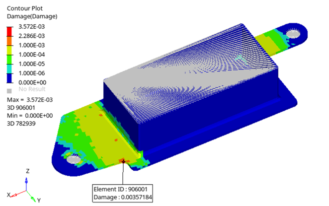
Review the Results
-
From the OptiStruct panel, click HyperView.
HyperView is launched and the results are loaded. A message window appears to inform of the successful model and result files loading into HyperView.
- Go to the Results tab.
- In the Results tab, select Subcase 5 (Vibration_Fatigue) from the subcase field.
-
On the Results toolbar, click
 to open the
Contour panel.
to open the
Contour panel.
-
Set Result type to Damage and click on
Apply to contour the elements.
Figure 5. Damage Contour Plot