
Couple MotionSolve with VEOS
MotionSolve interfaces with dSPACE VEOS, a PC-based simulation platform for ECU software validation.
VEOS lets you simulate many different models – from function models to networks of virtual ECUs, bus systems, and vehicle models. Its primary function is to simulate virtual processing units (VPUs) on a PC without the need for additional hardware. VPUs can represent virtual ECUs built by dSPACE SystemDesk, or system models built from Simulink models or functional mock-up units. With VEOS, you can interconnect these VPUs either directly or via virtual buses. Simulations running on VEOS can be accessed by the same tools as simulations running on hardware-in-the-loop simulators, allowing you to prepare simulation setups for hardware-in-the-loop simulations before the hardware is available.
The Value of MotionSolve and VEOS coupling
By coupling MotionSolve with VEOS, complex multi-physical systems can be studied with a focus on communication. In this coupling, MotionSolve models the mechanical system interacting with controllers or other systems in VEOS. For example, this could be a vehicle maneuvering through a tight obstacle course balanced by an electronic stability program (ESP). The vehicle sends information, like vehicle heading, steer angle, tire slip, and yaw rate, to the controller. The controller computes the necessary brake power for each wheel based on these inputs and returns it to the vehicle model to prevent over-/understeering.
Implement Coupling
The coupling between MotionSolve and VEOS is achieved via co-simulation between the two products. Both products run in parallel, each on their own process.
The interface between MotionSolve and VEOS is defined by inputs and outputs in each system. For MotionSolve models, special modeling statements, such as Control_PlantInput and Control_PlantOutput, are added to specify its inputs/outputs. These statements reference variables that are either used as inputs to the model (for example, forces or torques) or measure outputs (for example, displacements or velocities).
MotionSolve is coupled to VEOS either through FMU or Simulink S-function.
FMU Coupling
MotionSolve Models as a Functional Mockup Unit (FMU) describes the process of how to export a MotionSolve model as an FMU. This FMU can then be imported into VEOS. Please follow the VEOS manual on how to import FMUs.
S-function Coupling
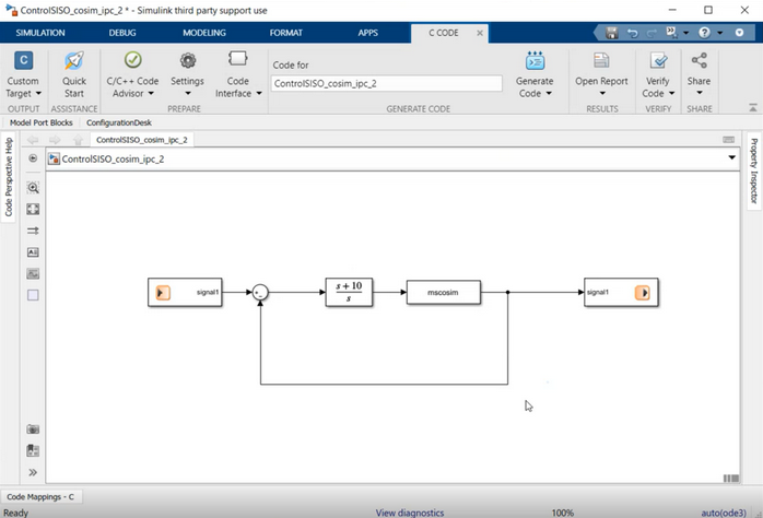
MotionSolve and Simulink Co-simulation Overview provides an explanation on how to embed a MotionSolve model as a plant using S-functions (System Function) in a Simulink model. Tutorial MV-7002: Co-simulation with Simulink has step-by-step instructions on creating S-functions from MotionSolve models. This tutorial explains specifically how to set up environment variables, add necessary MotionSolve binaries to MATLAB paths, and include the MotionSolve plant (S-function with the name mscosim) to a Simulink model.
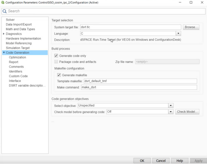
After you have created a Simulink model that includes a MotionSolve plant, you have to add VEOS specific Input and Output signals to the model (see the VEOS manual) and generate a Simulink Implementation Container (SIC) from it using Simulink’s Code Generation. The compiler has to be 64-bit, with the target file set to dsrt.tlc (see figures below).
- MS_VEOS_INPUT_FILE: defines the path to the MotionSolve input file
- MS_VEOS_OUPUT_FILE: defines the path to the folder where MotionSolve writes the results.
Output
Both solvers generate results for their respective models that can be post-processed within their own software.