Altair MotionView 2024 Release Notes
Altair Multibody Solutions 2024 Release Notes
Highlights
The Altair Multibody Solutions 2024 release includes the following enhancements and
bug fixes to MotionView and MotionSolve:
- Undo and redo (MotionView)
- Frequency Response Analysis (MotionView/MotionSolve)
- Experimental – Belt pulley with substructured flexible bodies (MotionView/MotionSolve)
- Experimental – Real-time simulations for vehicle models (MotionSolve)
- Dual Motor Electric Powertrain (Vehicle Tools Extension)
- Cables Library (Machinery Tools Extension)
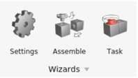
- Wizard modeling changes (MotionView)
New Features
- Undo and Redo (MotionView)
- It is possible to undo an entity creation, modification, and deletion
within a MotionView session. Use Ctrl+Z to undo and Ctrl+Y to redo a
previously undone action.Note: The Undo functionality is not available in dialogs.
- Frequency Response Analysis (MotionView/MotionSolve)
- The Frequency Response Analysis (FRA) feature has been available in
MotionSolve since 2023.1. MotionView now offers UI support to set up and
execute such an analysis.
- A FrequencyInput entity is available to define inputs to the
Frequency Response Analysis.
Figure 1. 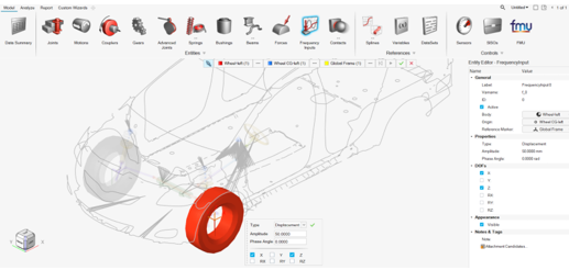
- Supported input types: Displacement, Velocity, Acceleration or Force.
- The input is in the frequency domain and is provided with an amplitude value, phase angle, and direction (DOFs).
- The Analysis Entity Editor supports these analysis types:
FrequencyResponse and Static+FrequencyResponse.
Figure 2. 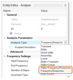
- A FrequencyInput entity is available to define inputs to the
Frequency Response Analysis.
- Experimental – Belt Pulley with Substructured Flexible Bodies (MotionView/MotionSolve)
- A new belt formulation, called Substructured Flexbodies, is now available as an experimental feature under the Belt Pulley system creation tool. In this formulation, the belt is modeled as a series of linear (CMS) flexible bodies connected by fixed joints. This method offers a faster solution compared to NLFE formulation and with a higher fidelity than a discretized rigid bodies formulation.
- Experimental – Real-time Simulation for Vehicle Models (MotionSolve)
- MotionSolve now supports real-time simulation for car models created using the MotionView wizard. You can activate this functionality with a switch in MotionView, eliminating the need for manual model reduction to achieve real-time performance. Models with flexible bodies, complex geometries, and a large number of degrees of freedom can be simulated in real-time with a click. In this context, the term "real-time" implies that the ratio of wall time required by the MotionSolve simulation versus specified end time is less than 1. It's important to note that, as this is an experimental feature, not all functionalities in the wizard are supported, and you may experience non-real-time performance or simulation failures. However, these issues will be addressed in future releases. In the meantime, you can disable the real-time feature if needed.
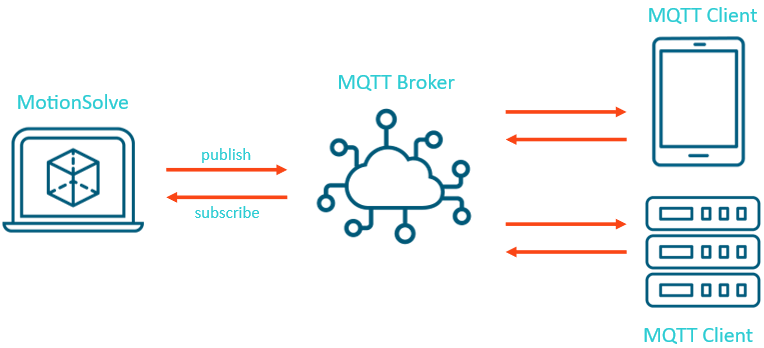
- MQTT Protocol (MotionSolve)
- MotionSolve now supports the MQTT protocol through its msolve API. MQTT, which stands for Message Queuing Telemetry Transport, is an OASIS standard messaging protocol developed for the Internet of Things (IoT). It is designed as a lightweight publish/subscribe messaging transport that enables remote devices to communicate with minimal code footprint and network bandwidth. MQTT has gained widespread adoption across various industries, including automotive, manufacturing, telecommunications, oil and gas, among others. The MQTT support in msolve facilitates bi-directional messaging between a MotionSolve model and other virtual or physical devices via a broker. This capability enables easy broadcasting of signals to groups of devices, making it a valuable feature for IoT applications.
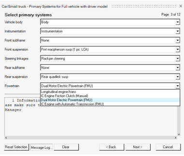
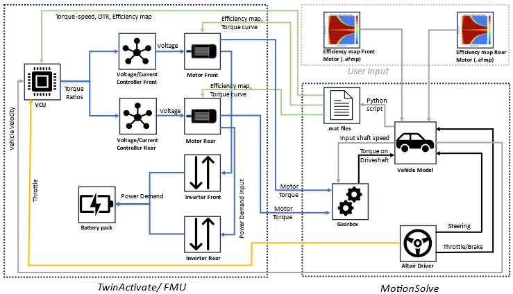
- Dual Motor Electric Powertrain (Vehicle Tools Extension)
- MotionView added the option to include a Dual Motor Electric Powertrain (FMU) model in the Car/Small truck vehicle library. This option is available for the “Full vehicle with Driver” and “Four wheel drive” driveline configurations and is accessible under the Assembly Wizard's Powertrain menu.
Enhancements
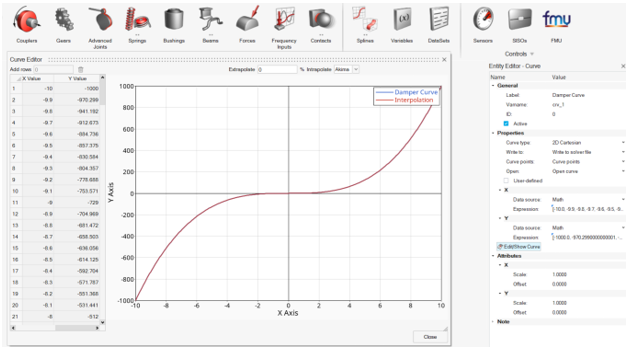
- Entity Editor for Curves
- The Curve entity now has an Entity Editor alternative to the panel. The editor also has a new Edit/Show Curve dialog to visualize the curve and edit it (only for curves with Data source set to Values).
- Wizard Libraries (MotionView)
- An Example Wizard in included in the Wizard library. You can use this library to create your own Wizard library. The Vehicle libraries that were included with the standard installation are now part of the Vehicle Tools Extension. This extension can be turned on from the Extension Manager, which is accessible through .
- Python API Updates (MotionView)
- Python APIs are now available to register in the Wizard library. The following API commands can be used under the mview module to register and set the Wizard library.
- Cosin F-Tire Version 2024-1 (Vehicle Tools Extension)
- Altair MotionSolve now supports the updated version of Cosin F-Tire 2024-1 that is used in vehicle simulations.
- Track Builder – Symmetric Track and New Outputs (Vehicle Tools Extension)
- Increasing the efficiency of the track modeling process, a symmetry option was added in the to automatically create both left and right track systems.
- Report Template for Kinematic and Compliance (KnC) Events for Half-vehicle Models (Vehicle Tools Extension)
- Previously, a new vehicle Kinematic and Compliance event was introduced in the Entity Browser with a significant workflow improvement on the event parameters. In that version, the automated report was available only for 2-axles, or 4-wheeled vehicles.
- Define Length of Soft-Soil Road Graphics (Vehicle Tools Extension)
- A new argument is now available to be used in the soft-soil road files to specify the length of the road graphics from the road reference marker.
- MIN_RADIUS Parameter to Improve Lane Change Maneuvers for Leaning Vehicles (Vehicle Tools Extension)
- The “MIN_RADIUS” attributes has been added to the Lane Change and Slalom events for leaning vehicles (Two-wheelers and others). This attribute can be used to specify a minimum radius along the planned path, which the control algorithm uses internally to design and fit a spline for the path follower control.
- MotionSolve FMU Path (MotionSolve)
- While running the MotionSolve FMU, all paths and environmental variables are now derived from the ALTAIR_FMU_ROOT to avoid setting multiple paths.
- Extend Usage of Multiple Post User Output Request with ID (MotionSolve)
- MotionSolve supports multiple post user output requests with ID, allowing you to write multiple custom output results in different forms like files, plots, and animations.
Changes
- Abaqus Solver Mode Deprecated
- The ABAQUS solver mode has been deprecated.
- NLFE Spring and NLFE Stabar Features Discontinued (MotionView)
- The tools to create a Spring and Stabilizer bar using NLFE have been discontinued.
- Multi-disciplinary Tools Extension (MotionView)
- The Multi-disciplinary Tools preferences is now available as an extension that can be downloaded from Altair Exchange and added via the Extension Manager.
- Export to MotionSolve Python (MotionView)
- MotionView uses MotionSolve's Python API, msolve, to solve models live and optionally offline (non-default). Additionally, you can export a Python solver deck using . Previously, there were two distinct styles of writing these Python files. The live run used a flat, non-parametric style of solver deck, while the offline run and export used a style that preserved the parametric relationship between entities.
- CAD Translator Update
- The third-party component used in translating various CAD formats, except Parasolid (STEP, IGS, CATIA, and so on, has been upgraded to a newer version. This upgrade addresses issues with slower CAD reading and poor geometry translations seen previously.
- Static Load Analysis in the Entity Browser (Vehicle Tools Extension)
- The Static Load analysis for the half-vehicle models created using the Car/Small truck and Heavy truck libraries is now included in the Entity Browser under .
- Tire Envelope Analysis in the Entity Browser (Vehicle Tools Extension)
- The Tire Envelope analysis for the half-vehicle models created using the Car/Small truck and Heavy truck libraries is now included in the Entity Browser under .
- Complete Workflow for Half- and Full-vehicle Analysis (Vehicle Tools Extension)
- With the Static Load and Tire Envelope analysis moving to the Entity Browser with parameters editable in the Entity Editor, the support for the Analysis Task Wizard is being removed in this release.
- Changes in CAD/FE Import Using HyperMesh
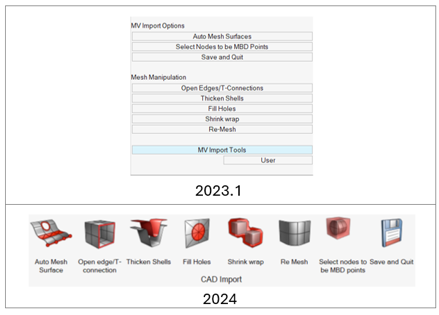
- The Utility menu in HyperMesh that appears while importing CAD/FE using HyperMesh in the interactive mode has been migrated to a MVUtils ribbon.
- Organized Binaries (MotionSolve)
- Organized verticals and tire related binaries are now under the msauto folder to avoid conflicts from third-party binaries.
Extensions
- Cables Library (Machinery Tools Extension)
- The Machinery Tools extension version 2.0 is now available on . In addition to bearings and gear libraries available in version 1.0, this version adds the Cables library.
Resolved Issues
- Analysis end time in the Entity Editor does not reset to the default after performing .
- Segmentation error when creating a system after creating other entities and using the Model Wizard.
- Solver_Filename and Solver_File_basename datamembers are not set when the solver deck is exported/run using Python.
- Solver_Filename and Solver_File_basename datamembers are not set correctly when a Template is pre-evaluated during the export of a solver deck.
- Application error when saving an external definition-based analysis.
- Double-clicking on a rigid group does not bring up its edit context menu.
- The CreateBlankModel TCL command crashes MotionView.
- The MarkerPair and BushingPair Entity Editor does now show Orientation information after switching sides.
- System attachment of type Dataset cannot be resolved using the Advanced selection dialog in the Entity Editor.
- Resolving a marker collector in the guidebar to an attachment's attribute sets it to the marker resolved and not as attachment’s attribute.
- Point coordinates are modified when orienting a marker that refers to the point for its orientation.
- Node tolerance information for the flexbody input in the Nodes and Modes dialog is not saved.
- Component names with backslash and spaces are not handled correctly during export to a solver.
- Curve created using Create line from points does not maintain its parametric relation with the points.
- User expression is not displayed in the compliant Joint and Bushing Entity Editor.
- Static hold option in the FMU Entity Editor gets reset after a change.
- The Model tree in the FMU Export dialog appears empty after loading the Vehicle Tools Extension.
- The Solver Array editor Plant Input/Output shows the solver variable button with the wrong default count.
- Application error in the Python window when changing the node tolerance in the Flexbody Nodes and Modes dialog.
- Curve extracted using faces is not to properly scaled.
- Asymmetric bush pair on one side displays a curve that is selected on the other side.
- "Run Offline" cannot be changed from the Run Motion Analysis dialog box if you have set it in .
- Action-only guidebar in the Forces context is not restored when the Action only check box is turned off and on.
- Changing the variable name of an NLFE sets the entity properties back to the default values.
- Local file widget in user-defined properties fails to accept a string as an input for the DLL name.
- MotionView crashes on a live run when a body refers to a non-existent point as CG.
- Expression using getnodecoordinates is not evaluated when the model is loaded or when flexbody is updated.
- The shortcut key Ctrl+E for Export Solver Deck does not work.
- Incorrect unit text in the Entity Editor fields when using centimeter as the length unit.
- MotionView crashes when adding an FMU generated from SmartUQ.
- hide_in_post for Outline graphics does not work.
- User-defined Template is not executed during a live run or offline run with Python.
- Live run does not create a .meta file when the model contains force outputs on bodies.
- Box graphics orientations are sent incorrectly to msolve Python.
- Damper graphics are not sent to the solver.
- Model containing an NLFE does not run.
- Loading a model with flexbodies referencing previous results may cause a crash.
- Vehicle model with an N-post event fails to run live.
- Runs in different folders appear under a different tree under the Run History.
- Rerun of models with a changed end time shows incorrect animation in the Results Review.
- Points at interface nodes are not created under the parent system of the flexbody.
- Making Point designable causes MotionView to crash.
- Two-wheeler Lane Change events fail when the lane parameters are resulting in very tight turns for considerable velocities.
- KnC and n-Post events Jacks are not detecting the tire radii properly to place the posts at the contact patch.
- Suspension models containing dual tires were not properly supported by the n-Post vehicle events. Dual tires were replaced with a single tire.
- Initial spike in acceleration signals for models that employ Siemens tires with USE_MODE = 514/534.
- During EDEM co-simulation, the force calculation for rigid bodies were done similar to flexible bodies based on forces on each triangle, which impacted the performance on the rigid models. With the current MotionSolve version, the forces from EDEM are calculated for the entire geometry for rigid bodies since they do not deform.
- Removed EDEM2H3d converter since HyperView natively supports reading EDEM models and results.
- Fixed the missing data, which were not saved to an XML file while using save_increment.
- MotionSolve-EDEM co-simulation issue, where MotionSolve was not responding to models containing flexible bodies with delayed start co-simulation (when the co-simulation start time > 0).

