Manage Penetrations/Intersections
Check contacts, components, or groups for element penetrations and intersections using the Penetration tool.
Penetration and intersection can be used individually or collectively. Penetration is defined as the overlap of the material thickness of shell elements, while intersection is defined as elements passing completely through one another.
-
From the Validate ribbon, click the Penetration
tool.
Figure 1. 
The guide bar and Penetrations Browser open. -
Set up the Penetration Check and check for intersections/penetrations using the
embedded algorithm.
-
From the guide bar, click
 and select
Embedded Algorithm for Check method.
Restriction: This is only for the LS-DYNA profile.
and select
Embedded Algorithm for Check method.
Restriction: This is only for the LS-DYNA profile. -
From the guide bar, click and adjust the
Minimum Depth to filter out penetrations with lower penetration depth
values.
-
For Boundary shell edge treatment, select a treatment algorithm for the
boundary shell edge.
- Choose Flat edges to consider external
borders of the components flat.
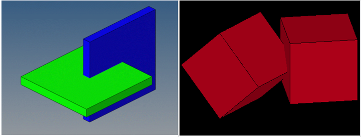
Figure 2. Flat Edges 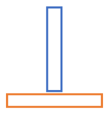
- Choose Rounded edges to extend external
borders of the component by a cylinder having the diameter of
the component thickness.
Figure 3. Rounded Edges 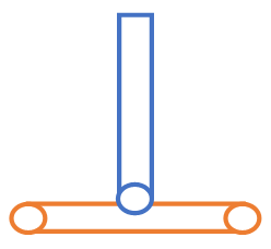
- Choose Flat edges to consider external
borders of the components flat.
-
From the guide bar, click
 Check.
Once the check is complete, the browser populates with detected intersections and/or penetrations.
Check.
Once the check is complete, the browser populates with detected intersections and/or penetrations.Figure 4. 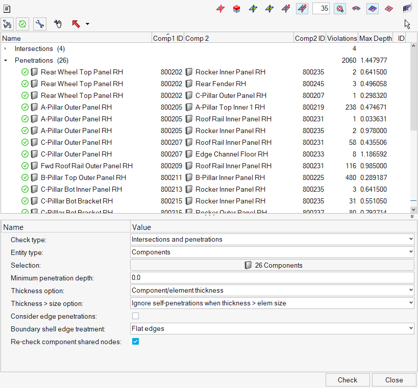
-
From the guide bar, click
-
Review the penetrations/intersections using the view controls legend.
Figure 5. 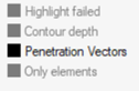
- Highlight failed: Highlights all elements that caused penetrations or intersection when you select a component pair the browser.
- Contour depth: Displays a color gradient of the penetrating elements in the selected component pair, which indicates the severity (degree) of penetration for the interacting elements. This mode is not available for intersections because their depth cannot be determined.
- Penetration Vectors: Displays individual vectors for each penetrating
element in the component that you select in the browser. These vectors
indicate the direction and depth of the penetration for both the
selected component and its interacting components.Note: If you want to view the vectors in a fixed size of his choice, you must adjust the Penetration vector size from the guide bar under.
This mode is not available for intersections because their depth cannot be determined.
- Only elements: Masks everything in the model, including the interacting components, except for the specific elements that penetrate or intersect.
-
Fix the penetrations/intersections.
To fix Do this Manually - Select groups/components/parts to fix in the Penetration Browser.
- Right-click on the pair, and select Manual
Fix from the context menu.Note: You can also select the pair in the Penetration Browser and clickNodes list from the penetrations are automatically selected. The Manual Fix move tool opens and will be used to manipulate nodes, elements to remove the penetrations, or intersections.
 on the
guide bar.
on the
guide bar. - From the guide bar, select
Recheck to recheck that the
intersection/penetration no longer remains.
Automatically - Select groups/components/parts to fix in the Penetration Browser.
- On the guide bar, click
Fix all.Note: You can also right-click the pair in the Penetration Browser and select Auto fix from the context menu.
Tip:- If a component is intersecting with another, right-click on the component and select Find Matching Penetrating Component Pair from the context menu to find the same pair of components in the penetrations list. If the pair does not penetrate, a message will display.
- To keep a specific component from changing when performing
de-penetration fixes, right-click on that component and select
Lock Component from the context menu. A red padlock displays on the
component name in the browser to indicate that it has been locked.
The nodes in a locked component cannot be moved by the Collision
tool. To unlock, right-click a locked component and select
Unlock Component from the context menu.
Figure 6. 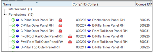
- Sort the columns in the browser by clicking the column headings. For example, clicking the Violations heading sorts the parent components according to their number of violations. A small triangular arrow in the column heading indicates whether the components are sorted in ascending or descending order; repeated clicks toggle between these two options.
-
Set up the Penetration Check and check solver output files for penetrations
using the Solver output file reader method.
Restriction: This capability is only for the LS-DYNA profile. It reads the LS-DYNA message or .d3hsp file containing the contact penetrations information and populates those penetrations in the Penetration Browser.
-
From the guide bar, click .
-
From the guide bar, click
Overview
The Penetration Check tool in HyperMesh is designed to mimic the respective Finite Element solver on hand to the maximum extent possible. This way, identified initial penetrations are almost identical to those detected by the solvers themselves.
Most Finite Element solvers encounter two types of collisions: penetrations and intersections.
Penetrations
Penetrations themselves are broadly divided into two categories: Node to Segment and Edge to Edge penetrations. Most commercial Finite Element solvers offer interfaces that are Node to Segment only, or Edge to Edge only, or more often than not, a combination of Node to Segment and Edge to Edge.
- Node to Segment Penetrations
-
A node to segment penetration is encountered when a secondary node is spatially located within the thickness of a main segment:
Figure 7. 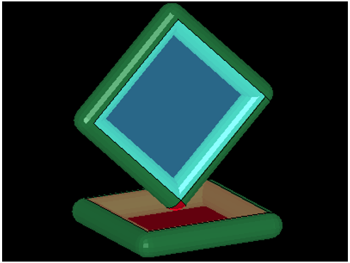
-
Figure 8. 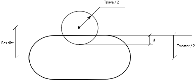
- In order to accurately identify nodal penetrations at segment boundaries,
like most commercial Finite Element solvers, the Penetration Check tool adds
virtual cylinders to the edges of segment boundaries as shown below:
Figure 9. 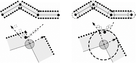
- For such modern interfaces in the Penetration Check tool:
- No virtual cylinders are added to the free/boundary edges of main shell elements.
- For secondary nodes of shell elements, the portion of the secondary
node spheres that lie outside the material of the shell elements are
ignored.
Figure 10. 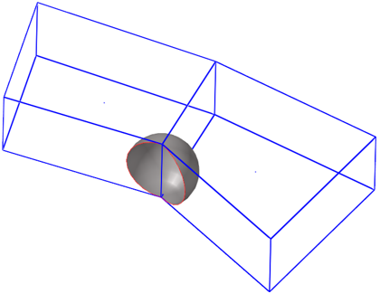
Note: A secondary node sphere should not be attached to more than two free/boundary shell edges. If attached to more than two, the secondary node sphere will be retained fully.
- Edge to Edge Penetrations
-
Edge to edge penetrations are those that occur when two distinct virtual edge cylinders of segments (that do not share a common node) interfere with each other.
Figure 11. 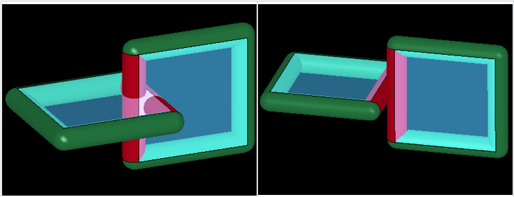
- Special Use Case
- Self-penetrations due to extremely thick segments. Some interfaces contain segments with large thicknesses (when compared to segment edge lengths). Depending on the type of penetration check performed, you might encounter penetrations within the same component.
- In a node to surface check, the secondary node sphere of one element
penetrates the virtual cylinder of the neighboring main segment.
Figure 12. 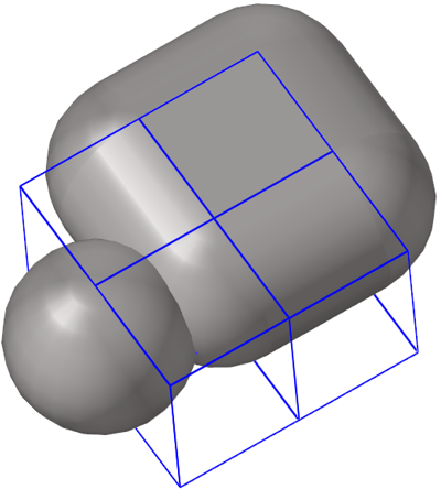
- In an edge to edge check, two virtual cylinders on opposite edges of the
same segment penetrate each other.
Figure 13. 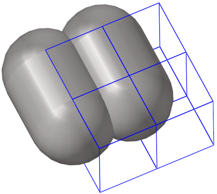
Intersections
Intersection checks are not a function of solver parameters and are, therefore, user-profile agnostic.
Intersections are not reported by most solvers. However, their presence will lead to severe issues during analyses, and should therefore be avoided at all costs.
Supported Solver Contacts and Parameters
In this section you will find contact and parameter information for the LS-DYNA, PAM-CRASH, and Radioss solver cards.
LS-DYNA Solver Contacts
| Group Type | Node to Surface | Edge to Edge | N2S Treatment when thickness > edge length |
|---|---|---|---|
| SINGLE_SURFACE | Yes | No | Optional, 40% of minimum edge length |
| AUTOMATIC_GENERAL | Yes | Yes | Optional, 40% of minimum edge length |
| NODES_TO_SURFACE | Yes | No | None |
| SURFACE_TO_SURFACE | Yes | No | None |
| SINGLE_EDGE | No | Yes | N/A |
PAM-CRASH Solver Contacts
| Group Type | Node to Surface | Edge to Edge | N2S Treatment when thickness > edge length |
|---|---|---|---|
| CNTAC Type 33 | Yes | No | Ignore neighborhood penetrations |
| CNTAC Type 34 | Yes | No | Ignore neighborhood penetrations |
| CNTAC Type 36 | Yes | No | Ignore neighborhood penetrations |
| CNTAC Type 37 | Yes | Yes | Ignore neighborhood penetrations |
| CNTAC Type 43 | Yes | Yes | Ignore neighborhood penetrations |
| CNTAC Type 46 | Yes | Yes | Ignore neighborhood penetrations |
Radioss Solver Contacts
| Group Type | Node to Surface | Edge to Edge | N2S Treatment when thickness > edge length |
|---|---|---|---|
| /INTER/TYPE7 | Yes | No | Optional, ignore neighborhood penetrations |
| /INTER/TYPE11 | No | Yes | N/A |
| /INTER/TYPE19 | Yes | Yes | N/A |
| /INTER/TYPE24 | Yes | Yes | N/A |
LS-DYNA Solver Parameters
| Entity | Solver Parameters |
|---|---|
| *CONTROL_CONTACT | TH, TH_SF, SSTHK |
| *CONTROL_SHELL | CNTCO |
| *CONTACT | SST, SFST, MST, SFMT, SLDTHK, SOFT, THKOPT, SHLTHK, SHLEDG, SRNDE, MSTYP, SSTYP |
| *PART | OPTT, SFT |
| *SECTION_SHELL | T1, NLOC |
| *ELEMENT_SHELL | THIC1, THIC2, THIC3, THIC4, OFFSET |
PAM-CRASH Solver Parameters
| Entity | Solver Parameters |
|---|---|
| CNTAC / | Hcont, ITPRT |
| PART / | TCONT, H |
| SHELL / | H |
| TSHEL / | H |
Radioss Solver Parameters
| Entity | Solver Parameters |
|---|---|
| /DEFAULT/INTER/TYPE7 | IGap, IRem_Gap |
| /DEFAULT/INTER/TYPE11 | IGap |
| /DEFAULT/INTER/TYPE19 | IGap |
| /DEFAULT/INTER/TYPE24 | IPen0, Inacti |
| /INTER/TYPE7 | IGap, GapMin, GapMax, FScaleGap, IRem_Gap, %Mesh_Size |
| /INTER/TYPE11 | IGap, GapMin |
| /INTER/TYPE19 | IGap, GapMin, GapMax, FScaleGap |
| /INTER/TYPE24 | IPen0, Grnod_Ids, GapMax_S, GapMax_M, PenMax, Inacti |
| /PART | Thick |
| /PROP | Thick |
| /SHELL | Thick |
| /SH3N | Thick |
Node List for Selected Penetrations
After performing penetration checks, detailed information regarding penetrating secondary nodes can be viewed in the node list for selected penetrations.
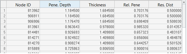
- Node ID
- IDs of the penetrating secondary nodes.
- Pene. Depth
- The maximum penetration depth for each secondary node listed.
- Thickness
- The gap (or thickness) value corresponding to the maximum of all penetration depths for each secondary node listed.
- Rel. Pene
- The relative penetration value for each secondary node listed. Relative Penetration = Penetration Depth / Thickness.
- Res. Dist
- The residual distance (or physical distance) between the mid-plane of the main segment and the center of the secondary node sphere.
- The secondary node is listed only once (despite multiple penetrations of multiple entities)
- The information listed against it corresponds to the maximum of all its penetration depths