Calculate Mass
Use the Mass tool to calculate the mass, center of gravity (COG), and moments of inertia (MOI) of the model.
-
From the Validate ribbon, click the Mass tool.
Figure 1. 
-
Click
 on the guide bar to set your
desired options.
on the guide bar to set your
desired options.
- Results type
- Defines the calculation as Mass, Center of Gravity and Inertia, or, Mass values only.
- Consider Time Step Mass
- Activates the calculation of solver numerical added mass due to
elemental time step.Restriction: This option is only valid in the Radioss and LS-DYNA profiles.
- Time Step Definition
- Set the method to retrieve the Time Step value.Restriction: This option is only valid in the Radioss and LS-DYNA profiles.
- Axes
- Defines the coordinate system axes in which the CoG and MOI values are computed. It can be the Global System or a Local System. If Local System is selected, a System selector appears on the guide bar to select the system in the model.
- MOI Center
- Defines the center location used for the moment of inertias calculation. It can be "at CoG" or "at System Center". Example: If the Axes option is set to Global System, MOI Center set to "at System Center" means that MOI values are calculated around (0,0,0) point location.
- Consider Lumped Mass
- Allows you to consider the lumped masses for the calculation of the CoG and MOI on the component level. This option is off by default, which respects the solver behavior.
- Show center of gravity
- Enables the creation of a marker in the modeling window to visualize the CoG location of the model.
- CoG Node
- Creates a free node at the CoG location of the model.
- Context numerical format
- Defines the format of the numerical format and precision of the values exposed in the results table
- Use the drop-down menu to group values based on assembly or include.
-
Click Compute.
The detailed mass values are displayed in a table.
Figure 2. 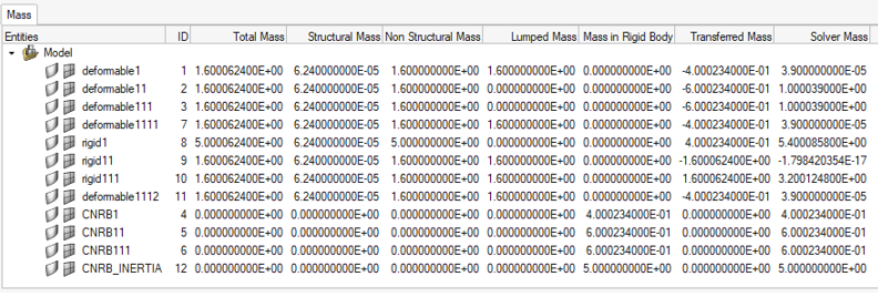
CoG and inertia selected as the Result Type, per component:Figure 3. 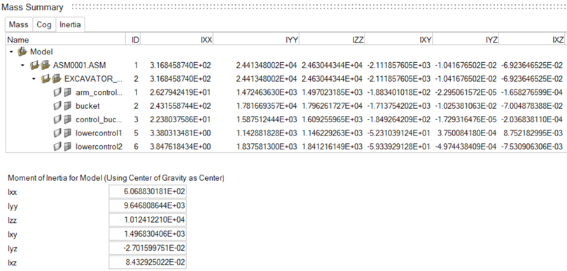
The relevant Total values are displayed at the bottom of the dialog.- Total Mass
- Represents the engineering mass as:
- Structural Mass
- Represents the physical mass of the structure, calculated from the property and material characteristics assigned to the FE mesh.
- Non-Structural Mass
- Represents the additional solver masses added on the structural mesh.
- Lumped Mass
- Represents the portion of the non-structural mass, which is distributed on structural nodes.
- Mass in Rigid Body
- Represents the mass of the nodal rigid body elements in the collector.
- Transferred Mass
- Represents the nodal mass transferred to the nodal rigid body elements or rigid Parts.
- Solver Mass
- Represents the mass as it is calculated by the solver.
Figure 4. 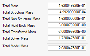
- Total Mass
- Represents the total engineering mass of the model and is the sum of the values in the Total Mass column of the table.
- Total Structured Mass
- The sum of the values in the Structural Mass column of the table.
- Total Non-Structured Mass
- The sum of the values in the Non-Structural Mass column of the table.
- Total Rigid Body Mass
- The sum of the Mass in Rigid Body column and represents the total mass of the nodal rigid body elements in the model.
- Total Transferred Mass
- The sum of the Transferred Mass column of the table.
- Total Solver Mass
- The sum of the Solver Mass column of the table.
- Total Model Mass
- Represents the final total mass of the model as it is calculated by the solver: