Create Axisymmetry
Create axisymmetry entities using either cross sections or selected planar surfaces.
-
From the Axisymmetry ribbon, click the Axisymmetry
tool.
Figure 1. 
-
Use the drop-down on the guide bar to select a creation
method.
- Cross Section: define a working plane as a finite cross section. The intersection with selected solids becomes the primary representation of the axisymmetric surface.
- User Surfaces: select planar surfaces as primary representation. A deep copy is used and modified by further imprint operations.
-
Select solids to reduce.
Axisymmetry entities keep track of selections. In the event of solid being split, it is important to select all solids that represent the 360° sector to reduce. These solids will then be considered during the Volume reduction factor calculation by ray tracing.Selecting solids automatically selects an axis of rotation.
- Optional: To change the axis definition, click Axis on the guide bar then left-click in the modeling window
- Optional:
Orient the axis and the model using the options in the microdialog.
Click X, Y, or Z to align to the global axes. Click
 to define target model orientation with the Vector tool.Note: Using these options not only change the axis but performs a global transformation on the entire model as well.
- In Figure 2 the original model orientation is random.
- You can select an axis along the part center as described before.
- Aligning to the global x-axis performs a global transformation using a 4*4 matrix that transforms the original axis position to match the desired axis.
Figure 2. 
-
Position the primary cross section at the desired location and resize.
Use the rotation manipulator to position the primary cross section at the desired location to define primary representation (not available for User Surfaces).
Optionally, reduce the size of the cutting plane using the plane handles.
Figure 3. 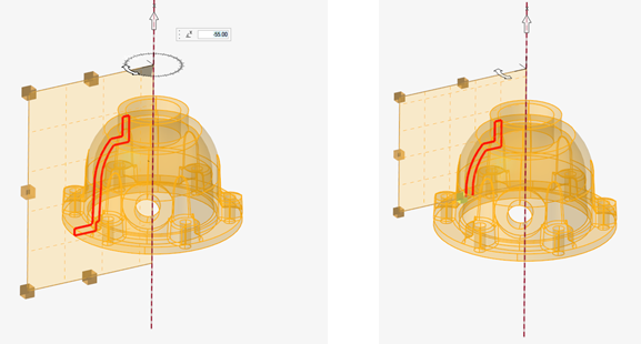
-
Click Create.
An Axisymmetry entity is created in the database and the workflow moves to edit mode. A Part entity is also created to hold the surface(s) created for axisymmetry representation.Tip: Click Back on the edit mode guide bar to return to the previous workflow. First reset and update the solid selection, then you can modify the plane location or axis.
-
Edit the Axisymmetry entity.
It is also possible to select an existing Axisymmetry entity in idle mode and push it to edit mode using the Edit Axisymmetry option in the context menu.
In this step, you can imprint geometric details to the primary surface using revolution about the selected axis.
Option Description Add Cross Sections With the Cross Section selector active, click  to add a secondary cross section entity. Use the rotation manipulator
and the dynamic preview to place it at the desired location.
to add a secondary cross section entity. Use the rotation manipulator
and the dynamic preview to place it at the desired location. It is possible to add multiple secondary cross sections sequentially.
Figure 4. 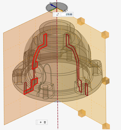
Delete Secondary Cross Sections In the event you want to remove a secondary cross section: - Graphically select a cross section to make it active.
- Click
 in the microdialog.
Imprint Surfaces or Lines As an alternate method, it is possible to select surfaces or lines to sweep around an axis and project onto the axisymmetry entity. - Set the selector type to surface or line and select entities.
- The imprint is updated onto the main surface. It may require some time for large models.
Surface selection and line selection are kept at the Axisymmetry entity level. Changing the type from Surfaces to Lines does not reset the surface selection (and vice versa). You need to reset or remove surfaces/lines from the selection to discard their projection.
Lines are really accounted when their projection leads to a closed contour that delimits new surfaces.
Imprint Solids In some cases, the assembly to represent as axisymmetric surfaces contains a collection of periodically distributed solids (such as the blades of a turbomachine in Figure 5). In this case, the original periodic solids do not need to be part of the solid selection in the Axisymmetry entity creation. Figure 5. 
Instead, you can select one instance of such solid as a Solid to imprint.
After Solid selection, a microdialog opens to define the number of instances (def 1), that is the number of repetitions around 360°. The solid is swept around the axis projected to the main surface. An extra parameter is saved at surface level to account for the volume reduction.
-
On the guide bar, complete one of the following:
- Click
 to apply and stay in the tool.
 - Click
 to apply and close the tool.
 - Click
 to exit the tool without applying.
- Click