
Trace on a Feasibility Analysis
Choose points, lines, or edges to measure how the forming process changes the blank. Tracers are useful to determine the best sized blank and understand how the material flows during the forming process.
- Run a forming analysis, or if a run already exists, the trace path will appear.
-
To see the path of a trace on the part, click
 in the Analysis Explorer.
- In the microdialog that appears, choose Tracing or Edge Analysis. If you select Tracing, choose Edge, Point, or Line to trace on the part; if you select Edge Analysis, you must choose Edge to analyze.
-
Make the selection on the part, then press
 on the Animation toolbar
to view how the selected edge/points/lines move in space over time.
on the Animation toolbar
to view how the selected edge/points/lines move in space over time.
- Optional:
Click
 to
define the orientation of a line projection.
Choose from
to
define the orientation of a line projection.
Choose from- Local blank normal (default) Project the line onto the blank based on the local normal of the sheet. Varies with location.
- Draw direction Use the draw direction of the current stage to project the line onto the sheet.
- Line normal Use the normal of the plane that contains the line.
- Optional:
Enable a full or partial trace path.
To see a full trace path of a line projection, right-click on the line to access the context menu and select Enable Trail, or enable it in the Property Editor.
The full trace path is enabled for a point projection by default. To see a partial trace path for a point, from the start to the current animation frame only, right-click on the path to access the context menu and select Disable Trail. The subsequent frames will not display the trail.
- Right-click and mouse through the check mark to exit, or double-right-click.
- Tracers are associated with part features. The tracer may be deleted if changes are made to the part feature or geometry associated with it.
- Tracers can be hidden or shown by clicking their icons in the Model browser or by using the context menu.
- You can change the color and line thickness of the tracer and its trace path in the Property Editor.
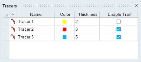
Tracers Table
The Tracers Table lists all of the tracers in your model and allows you to edit various attributes.
Location: Tracers tool, satellite icon ![]()
| To | Do this |
|---|---|
| Rename a tracer | Select the cell in the table and then click again to make the field editable. |
| Change the color | Select the color cell in the table and then select a different option from the color palette. |
| Sort a column | Click the column header. Click repeatedly to toggle between ascending and descending order. |
| Add or remove columns | Right-click on a column header. |
Shortcuts
| To | Do this |
|---|---|
| Select a reference part | While a tracer is selected, hold down the Ctrl key and left-click a part to act as the paper. |
| Exit the tool | Right-click and mouse through the check mark to exit, or double-right-click. |