Scheme
Overview
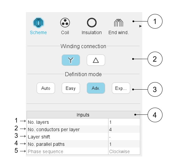
Here are below the winding scheme user inputs.
 |
|
|---|---|
| 1 | Sections to design the winding step by step. |
| 2 | Winding connection (Y – Wye or Δ - Delta) |
| 3 | Winding definition mode: Automatic, Easy, Advanced or Expert. See the below section dedicated to the construction of the winding architecture. |
| 4 | List of user inputs to define the winding architecture. See the corresponding definition below. |
Definition modes
There are four winding definition modes: Automatic, Easy, Advanced, and Expert. See below the corresponding illustration.
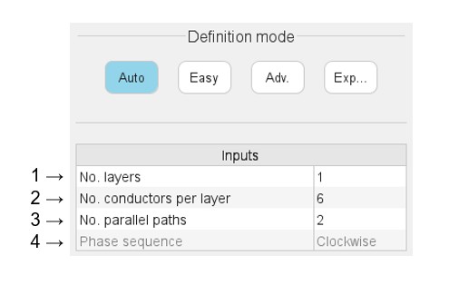
Automatic
 |
|
|---|---|
| 1 | Number of layers - 1 is the only value available for this mode |
| 2 | The number of conductors per layer must be even and limited to 30. An automatic drop-down list is provided. |
| 3 | Number of parallel paths. The possible numbers of parallel paths
are automatically computed and proposed to the user; 2 is the maximum proposed value according to the used hairpin pattern. When the user selects a number of parallel paths the connections on the winding scheme are automatically updated. |
| 4 | Definition of the phase sequence i.e. the rotation direction of
the Magneto-Motive Force (M.M.F): Clockwise or Counterclockwise. The
rotation direction is defined when facing the machine on the
connection side. The phase sequence is set to clockwise and cannot be modified in the current version (grayed field). |
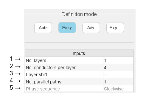
Easy
 |
|
|---|---|
| 1 | Selection of the number of layers. The number of layers is limited to 2. An automatic drop-down list is provided. |
| 2 | The number of conductors per layer must be even and limited to 30. An automatic drop-down list is provided. |
| 3 | The layer shift is defined by a number of slot pitch. It cannot exceed the number of slots per pole and per phase. (Only available with 2 layers). |
| 4 | Number of parallel paths. The possible numbers of parallel paths
are automatically computed and proposed to the user; 2 is the maximum value proposed according to the considered hairpin pattern. When the user chooses several parallel paths the connections on the winding scheme are automatically updated. |
| 5 | Definition of the phase sequence i.e. the rotation direction of
the Magneto-Motive Force (M.M.F): Clockwise or Counterclockwise. The
rotation direction is defined when facing the machine on the
connection side. The phase sequence is set to clockwise and cannot be modified in the current version (grayed field). |
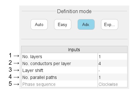
Advanced
 |
|
|---|---|
| 1 | Selection of the number of layers. The number of layers is limited to 2. An automatic drop-down list is provided. |
| 2 | The number of conductors per layer must be even. The user is free to choose the value they want. |
| 3 | The layer shift is defined by a number of slot pitch. It cannot exceed the number of slots per pole and per phase. (Only available with 2 layers). |
| 4 | Number of parallel paths. The possible numbers of parallel paths
are automatically computed and proposed to the user; 2 is the maximum value proposed according to the considered hairpin pattern. When the user chooses several parallel paths the connections on the winding scheme are automatically updated. |
| 5 | Definition of the phase sequence i.e. the rotation direction of
the Magneto-Motive Force (M.M.F): Clockwise or Counterclockwise. The
rotation direction is defined when facing the machine on the
connection side. The phase sequence is set to clockwise and cannot be modified in the current version (grayed field). |
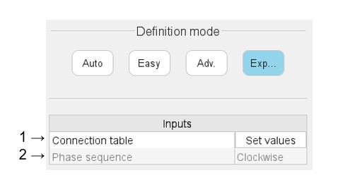
Expert
 |
|
|---|---|
| 1 | “Set values” means opening the dialog box to fill the connection table. See illustration below. |
| 2 | Definition of the phase sequence i.e. the rotation direction of
the Magneto-Motive Force (M.M.F): Clockwise or Counterclockwise. The
rotation direction is defined when facing the machine on the
connection side. The phase sequence is set to clockwise and cannot be modified in the current version (grayed field). |
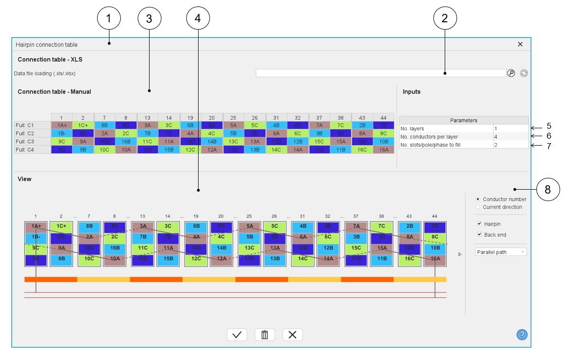
Connection table
Presentation
 |
|
|---|---|
| 1 | Dialog box to define a connection table with expert mode. |
| 2 | Field to upload a connection table defined into a *.xlsx file. |
| 3 | Box to manually fill a connection table or modify an uploaded one from a *.xlsx file. |
| 4 | Dynamic view of the hairpin winding updated in real time as a function of the filling status of the connection table. |
| 5 | Selection of the number of layers. The number of layers is limited to 2. |
| 6 | Number of conductors per layer (This value must be even). |
| 7 | Number of slots per pole and per phase to set. No more than 2 times the number of slots per pole and per phase. |
| 8 | Area to customize the view. For each elementary coil set in
parallel (A, B, C…):
|
Main rules
- Define the number of layers, the number of conductors per layer and the number of slot / pole / phase according to the expected hairpin winding configuration.
- Each parallel path (also called elementary coil) is characterized by a letter (A, B, C…, AA, AB,…).
- The parallel path A must begin by 1A+ or 1A-. 1 corresponds to the first
conductor number. Each added conductor increments the conductor number by
one.
- “+” or “-“ correspond respectively to the “clockwise” or “counterclockwise” direction of rotation of a parallel path (or part of a parallel path). Only the first conductor of a hairpin (odd number) can define the direction of rotation.
- The rotation direction is defined when facing the machine on the connection side.
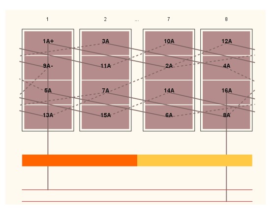
Example
How to define a parallel path composed of 16 conductors in which the first 8 rotate in the clockwise way (conductor 1 8) and the other 8 rotate in the counterclockwise way (conductor 9 16)?
The first conductor of the first 8 conductors must be defined as “1A+” to rotate in the clockwise direction.
Then the first conductor of the last 8 conductors must be defined as “9A-“ to rotate in the counterclockwise direction.