Connection table
Presentation
 |
|
|---|---|
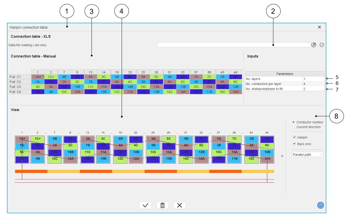
| 1 | Dialog box to define a connection table with expert mode. |
| 2 | Field to upload a connection table defined into a *.xlsx file. |
| 3 | Box to manually fill a connection table or modify an uploaded one from a *.xlsx file. |
| 4 | Dynamic view of the hairpin winding updated in real time as a function of the filling status of the connection table. |
| 5 | Selection of the number of layers. The number of layers is limited to 2. |
| 6 | Number of conductors per layer (This value must be even). |
| 7 | Number of slots per pole and per phase to set. No more than 2 times the number of slots per pole and per phase. |
| 8 | Area to customize the view. For each elementary coil set in
parallel (A, B, C…):
|
Main rules
Here are the main rules to fill the connection table or to define a *.xlsx equivalent
file:
- Define the number of layers, the number of conductors per layer and the number of slot / pole / phase according to the expected hairpin winding configuration.
- Each parallel path (also called elementary coil) is characterized by a letter (A, B, C…, AA, AB,…).
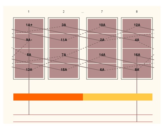
- The parallel path A must begin by 1A+ or 1A-. 1 corresponds to the first
conductor number. Each added conductor increments the conductor number by
one.
- “+” or “-“ correspond respectively to the “clockwise” or “counterclockwise” direction of rotation of a parallel path (or part of a parallel path). Only the first conductor of a hairpin (odd number) can define the direction of rotation.
- The rotation direction is defined when facing the machine on the connection side.
Example
How to define a parallel path composed of 16 conductors in which the first 8 rotate in the clockwise way (conductor 1 8) and the other 8 rotate in the counterclockwise way (conductor 9 16)?
The first conductor of the first 8 conductors must be defined as “1A+” to rotate in the clockwise direction.
Then the first conductor of the last 8 conductors must be defined as “9A-“ to rotate in the counterclockwise direction.