X-Factor
Definitions
 |
|
|---|---|
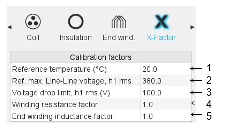
| 1 | The reference temperature. First, resistance values are computed by considering a temperature equal to 20°C. However, the user can also define his own reference
temperature to compute the corresponding phase resistance and
Line-Line resistance values. Note: This
reference temperature is used only in the winding design
environment. The test temperatures are defined in the test settings (refer to TEST chapter). |
| 2 | Reference maximum Line-Line voltage. It allows evaluating the voltage drop between the conductors. |
| 3 | Voltage drop limit between 2 superimposed conductors. This limit is given to better visualize the voltage threshold, which shall not be exceeded (see the displaying of colored fields in the table). |
| 4 | Setting of the “Resistance factor”. It allows adjusting the computation result of resistance with resistance measurement. Thus, the resulting phase resistance value is considered. |
| 5 | Setting of the “Inductance factor”. It allows modifying the
computation result of end-winding inductance. Thus, the resulting end-winding inductance value is considered. |