Scheme
Overview
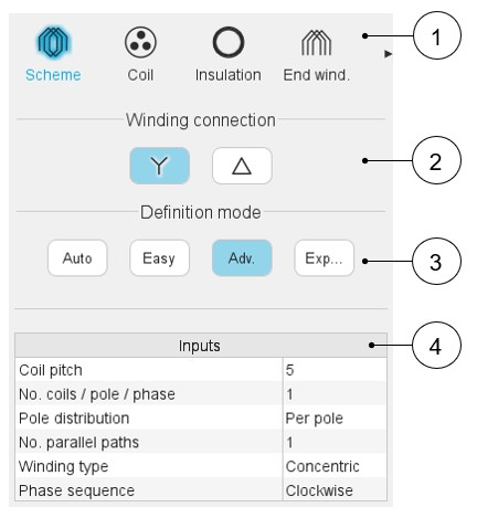
Here are below the winding scheme user inputs.
 |
|
|---|---|
| 1 | Sections to design the winding step by step. |
| 2 | Winding connection (Y – Wye or Δ - Delta) |
| 3 | Winding definition mode: Automatic, Easy, Advanced, or Expert. See the below section dedicated to the construction of the winding architecture. |
| 4 | List of user inputs to define the winding architecture. See the corresponding definition below. |
Definition modes
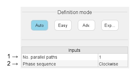
There are four winding definition modes: Automatic, Easy, Advanced and Expert. See below the corresponding illustration.
Automatic
 |
|
|---|---|
| 1 | Phase sequence (all modes).
Note: The rotation direction is defined
when facing the machine on the connection side. |
| 2 | Number of parallel paths (all modes). Note: The possible numbers of parallel paths are automatically
computed and proposed to the user. When the user chooses a number of parallel paths, the connections on the winding scheme are automatically updated. |
Easy
 |
|
|---|---|
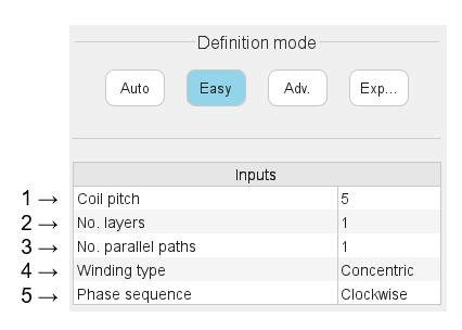
| 1 | Coil pitch = number of slot pitch between coil input and coil
output (Easy mode / Advanced mode). Note: The
proposed solutions depend on the number of slots, the number of
poles and the number of phases. Example 1: With 12 slots,10 poles and 3 phases, only one solution is proposed: a tooth winding. Example 2: With 48 slots, 8 poles and 3 phases, two solutions are proposed: 5 or 6. For various possibilities, a list of solutions is proposed. |
| 2 | Number of layers - 1 or 2 (Easy mode). Note: The proposed solutions depend on the number of slots, the
number of poles and the number of phases. Example: With 12 slots, 10 poles and 3 phases, only one solution is proposed: 1 layer. |
| 3 | Number of parallel paths (all modes). Note: The possible numbers of parallel paths are automatically
computed and proposed to the user. When the user chooses several parallel paths, the connections on the winding scheme are automatically updated. |
| 4 | Winding type - Lap or Concentric (Easy mode / Advanced mode). |
| 5 | Phase sequence (all modes) - Clockwise or Counter-clockwise. Note: The rotation direction is defined when
facing the machine on the connection side. |
Advanced
 |
|
|---|---|
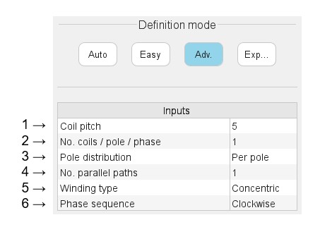
| 1 | Coil pitch = number of slot pitch between coil input and coil
output (Easy mode / Advanced mode). Note: The
user is free to choose the value they want. The possible
solutions depend on the number of slots, the number of poles and
the number of phases. |
| 2 | Definition of the number of coils per pole and per phase. |
| 3 | Definition of the pole distribution: Per pole or Consequent. |
| 4 | Number of parallel paths (all modes). Note: The possible numbers of parallel paths are automatically
computed and proposed to the user. When the user chooses several parallel paths, the connections on the winding scheme are automatically updated. |
| 5 | Winding type - Lap or Concentric (Easy mode / Advanced mode). |
| 6 | Phase sequence (all modes) - Clockwise or counter-clockwise. Note: The rotation direction is defined when
facing the machine on the connection side. |
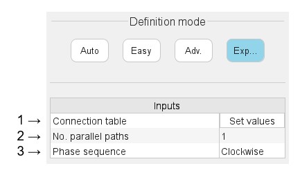
Expert
 |
|
|---|---|
| 1 | “Set values” means opening the dialog box to fill the connection table. See the table connection below. |
| 2 | Number of parallel paths. The possible numbers of parallel paths
are automatically computed and proposed to the user. When the user
chooses several parallel paths, the connections on the winding
scheme are automatically updated. See examples in Auto mode
chapter. Note: The complete list of the
possible numbers of parallel paths is proposed. Sometimes, the
number of parallel paths can be greater than the number of
possible duplications. In that case, the connection of the parallel paths is not displayed on the layout of the winding. |
| 3 | Phase sequence (all modes) - Clockwise or counter-clockwise. Note: The rotation direction is defined when
facing the machine on the connection side. |
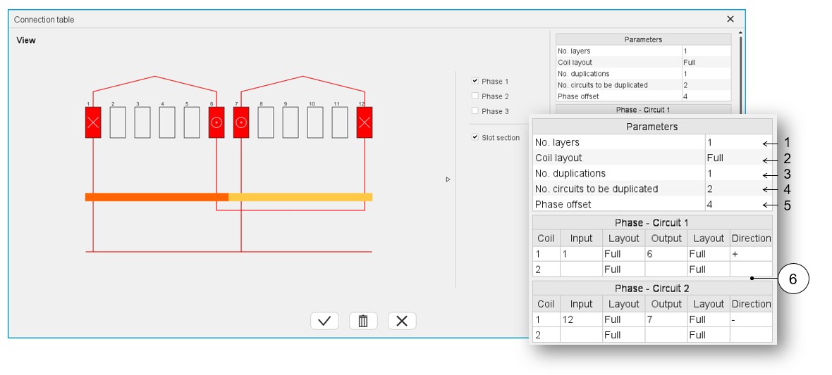
Connection table
Input parameters
 |
|
|---|---|
| 1 | Selection of the number of layers. The solutions depend on the
number of slots, the number of poles and the number of
phases. Example: With 12 slots,10 poles and 3 phases, only one solution is proposed: 1 layer. The three possible cases are illustrated in the Easy mode section. |
| 2 | Definition of the coil layout i.e. how the coil sections are
distributed into the slot. The three possible choices are:
The solutions depend on the number of phases, the number of slots and the number of poles. Example 1: With
12 slots, 10 poles and 3 phases, two solutions are proposed:
superimposed or adjacent. Note: in that
case, only toothed winding is relevant. This corresponds to
an adjacent coil layout. Example 2: With 48 slots, 8 poles and 3 phases, one solution is imposed: Full. |
| 3 | Definition of the number of duplications. This number is computed and proposed to the user. It depends on the number of slots and the number of poles. When the winding architecture to build is cut into several identical parts, the corresponding possible number of duplications are proposed (a short list). By selecting the number of duplications, the user must define only 1/n of the connection table. |
| 4 | The number of circuits to be duplicated represents the number of
elementary circuits to be defined inside each sector to be
duplicated. In this example 2 circuits are defined in the
represented sector. This is why there are 2 connection tables to be filled in. One for each circuit: Phase 1 – Circuit 1 and Phase 1 – Circuit 2 |
| 5 | Phase offset – See explanation and illustration below. |
| 6 | The connection table(s) must be filled in. 1 or 2, according to
the number of circuits to be represented inside the considered
elementary sector.
Then, another line is proposed to describe the next coil. |
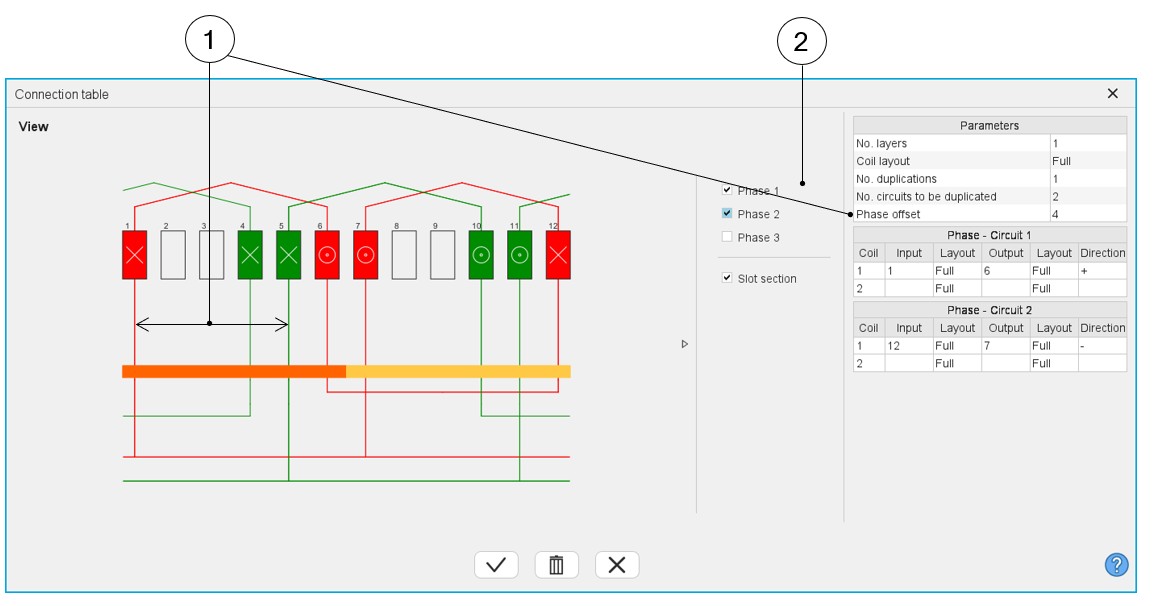
Phase offset parameter
 |
|
|---|---|
| 1 | Definition of the phase offset = number of slot pitch between each phase. |
| 2 | Make the phase visible or not. Note: All the
phases are identical. Phases 2 and 3 are identical to Phase 1
and are displayed in the winding by considering the phase
offset. |
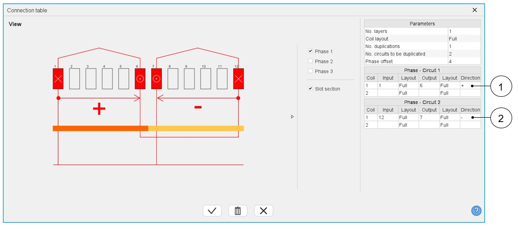
Winding direction for coils
 |
|
|---|---|
| 1 | Definition of a positive orientation of a coil, i.e., in the clockwise direction from the connection size (=ascending order of slot numbers). |
| 2 | Definition of a negative orientation of a coil, i.e., in the counterclockwise direction from the connection size (=descending order of slot numbers). |
Additional information
-
The real distribution of the parallel paths in the winding is taken into account for performing the tests. It is why one needs to know how the parallel paths are distributed. To do that, in the expert mode, to define the connection table, the user can define the number of circuits to be duplicated, and for that, he must fill in a connection table for each elementary parallel path.
Table 9. Dialog box for defining the connection table while using the expert mode 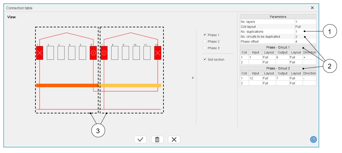
1 Number of duplications. See the definition in the table above. 2 Number of circuits to be duplicated. See the definition in the table above. 3 Representation of the two circuits inside the considered sector. Then, the list of possible number of parallel paths « No. parallel paths » adapts itself in function to the number of duplications « No. duplications » and the number of circuits to be duplicated « No. circuits to be duplicated ».
Here is the resulting layout of the winding architecture below. There are always 4 possible parallel paths. These circuits can be well connected.
Figure 1. Layout of the resulting winding architecture 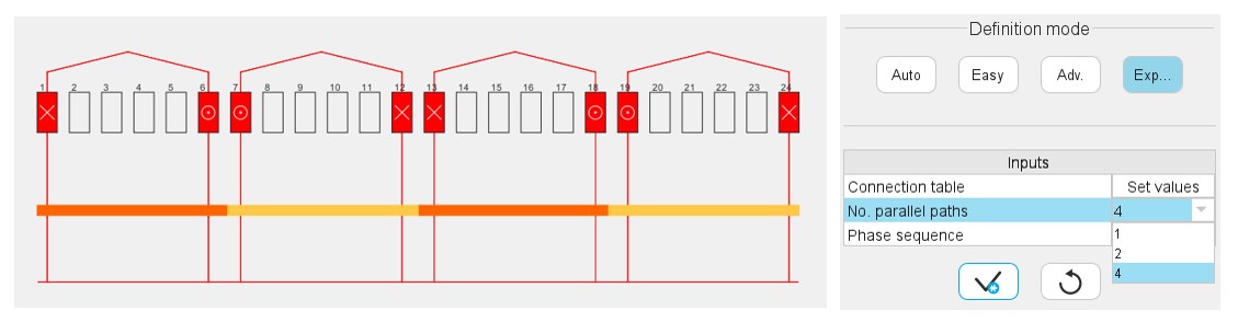
his modification is a problem for motors the number of parallel paths « No. parallel paths » of which is greater than the number of duplications « No. duplications ».
In that case, one has decided to modify the value of the « No. parallel paths » to make it take the value of the « No. duplications ».